
Installing A Gas Tap

Installing A Gas Tap
-1/7-
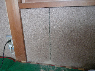
I consulted with a dealer about where to install a gas tap.
Our conclusion was to take off a part of clay wall close to the place where there was the gas meter outside. I undertook the work.
The photo shows how I started the work.
Using a drill I made a line of holes along the marked line in order to separate the part to be taken off from the body wall.
-2/7-
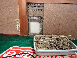
I broke off the wall carefully so that the work didn't damage other parts of the wall.
Clay taken off I made an empty space by cutting off a part of the bamboo mesh with a rotary grinding wheel.
Again the work shouldn't give damage to the body wall. I could do it successfully.
One mistake was a dust mask. Dust rose arond while cutting bamboo mesh. I put on a mask but it was rather late. I found later I inhaled a lot of dust. Inside of my nose was black.
-3/7-
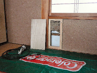
The opening is covered with a plywood panel which is screwed on to the frame inside the opening.
It took me a long time but I could make a stout frame which finally fitted tight into the opening.
-4/7-
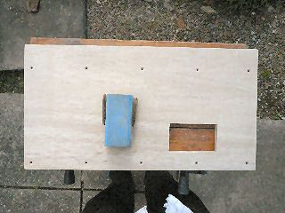
I made the small opening on the panel for the tap on the day it was installed.
A dealer man marked the place and the size very clearly.
I sandpapered the panel(the photo) for painting, which I did later on a warm day.
-5/7-
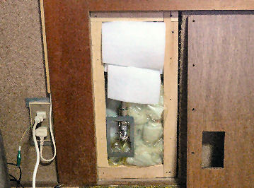
I filled the cavity with insulator in order to prevent dew condensation and a gap wind. The material was the remaining of what I used for my speaker systems as a sound absorber.
-6/7-
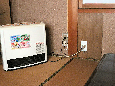
The tap was installed as in the photo.
Now the heater is easy and carefree to use. We keep old kerosine heaters only for the occasions needed in their rooms When they come back home.
-7/7-
Return to the listToilet Stool Gasket Replacement
-1/15-
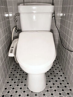
Steps of repair:
1. Close the water stopper.
2. Flush water and empty the toilet tank, then drain water in the toilet stool. I used a plastic manual pump for kerosene.
3. Take off the water pipe from the tank, then turn the nuts off the tank bottom in order to take it off the toilet stool.
4. Drain water from the washer toilet seat and take it off the toilet stool. See for details at "PANASONIC WASHER TOILET SEAT" in this site.
5. Turn off the bolts and nuts and take off the toilt stool.
6. Change gaskets.
7. Restore the toilet.
Above are the steps which may look simple but actual work is not as easy. Unexpected things may happen or you may dirty a floor or your clothes. You must take a measure for the odor, too. Plastic gloves and a sheet are musts.
-2/15-
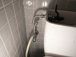
The photo is the part where water is fed to the tank. It had beeb changed from a normal pipe to the flexible one as I installed the washer toilet seat. The tank lid is taken off.
The flexible pipe is connected to the stopper by way of a junction that branch out to the washer toilet seat.
As you take off the flexible pipe, you have to be careful not to lose a gasket.
-3/15-
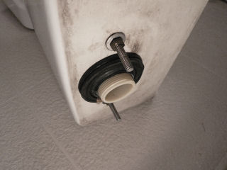
The tank bottom:
It is fixed to the stool by two bolts. The nuts were easy to loosen and the rubber gasket was still elastic.
There are hollows at the bottom inside where water remains a little even after flushing. You need to be careful not to spil it.
-4/15-
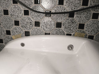
The bolts that fix a toilet stool.
The stool is bilaterally symmetrical. The front is right side in the photo.
The stool is fixed on to the floor with the smaller bolt(anchored bolt) on the left.
I had to break the anchored bolts as I took off the stool, about which I wrote at the bottom.
The bolt on the right is for unifying a stool and a drain pipe with a gasket in between by tightening a metal ring toward the stool, not for fixing it on to the floor. It is detached from the floor.
At this stage you mark accurate position to which the stool is placed back. I used yellow masking tape, which are not clear in the photo, though. Marking is neccessary by all means in order to set the stool at one go. The new gasket will be damaged otherwise.
The description above turned out to be wrong. You must read Re-repair at 14/15.
-5/15-
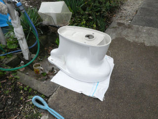
The stool is beeing washed.
You can't pump out all the water inside because of its siphon structure. So you have to be careful when you carry it out.
It will be difficult to wash it in a bath room. You have to repeat turning it over and over until dirty thing stops coming out.
After washing you dry it.
-6/15-
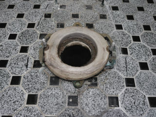
The loosened gasket from which the odor rose.
It had been loosened. The photo maybe too small to show how it is damaged.
It is designed to work in the way the protruded brim on the bottom of the stool presses down the gasket on the inner circumference. Unified tightly by bolts and nuts, the stool and the drain pipe become one so that it never leaks out bad water.
I noticed the stool was loose a little when I took it off. I surmised it might have kneaded the gasket. When setting it back you must check it is fixed tight both on to the gasket ring and on to the floor.
-7/15-
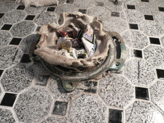
A gasket is beeing taken off.
To stop the odor a piece of crumpled paper is put into the drain pipe.
I used a minus driver to peel it off the pipe end and a metal ring.
In order to let a new gasket fit tight on to the place, I took off the old gasket elaborately.
-8/15-

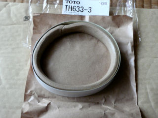
A new gasket made of putty.
I bought two at a net shop for 1194yen includeing postage.
The gasket is set inside a piece of cardboard ring. The inside surface of the ring is coated so that putty won't stick to it. It is useful. You can use it in the next step.
-9/15-
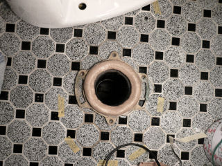
In applying the new gasket, you have to make it flat like a ring of canned pineapple, then shape it to a proper size. You'll find the coated cardboard paper very handy in shaping the gasket.
When setting back the stool, you use the marks and place it down exactly onto the right place at one go in order not to damage the new gasket.
If you failed, you have to shape the gasket again.
-10/15-
-11/15-
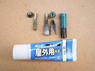
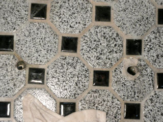
The broken bolts and an anchor, a filler and a new anchor.
A part of the bolt at top left remained in the anchor.
The bolt on its right came out with its anchor before it was broken.
The heads of both bolts were torn off when forced to turn. Holes for the cap made them weak.
Repair of anchors took considerable time and energy. It was an unexpected happening that offen accompanies D.I.Y
I had to wait for the filler to harden and the toilet repair took two days.
-12/15-
-13/15-
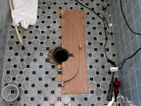
-15/15-
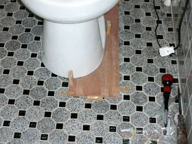
I installed three sliding guides on the outer guide so that I can let down the stool along those guides just at the right position.
The photo shows how the stool was set. As I set the stool in such a way I could experienced for the first time the feeling of pressing the putty gasket in the right position, which I didn't last time.
Now I declare with confidence the completion of the repair.
-15/15-
Return to the listRenovation Of Garage
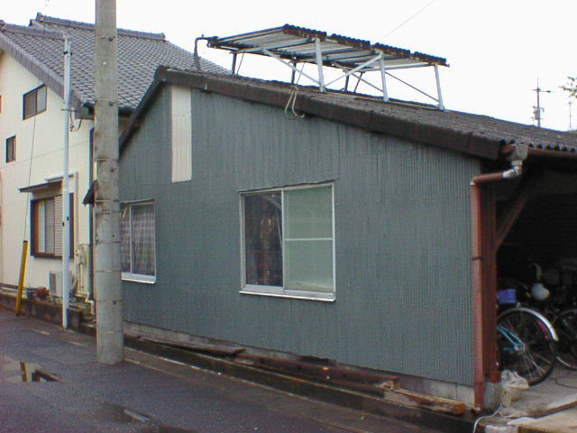
My father built this garage soon after our new house was built. A part of the garage is a storeroom. The photo shows its north side after remodeling.
As my brother, who lives next door rebuilt his house, I had to remodel the garage, for the rebuilding blocked the west side of the garage, the entrance side.A big carphtry it became. I hadn't imagined the work to be done by myself.
It had turned out to be my weekend carpentry because the cost estimated by a professional carpenter was too expensive.
The shock of the estimate made me decide to do it by myself. A man, triggered by a big shock, often betrays his hidden power. Besides, I used to watch, though unconsciously, my father's work, rebuilding work wasn't any difficult.
-1/10-
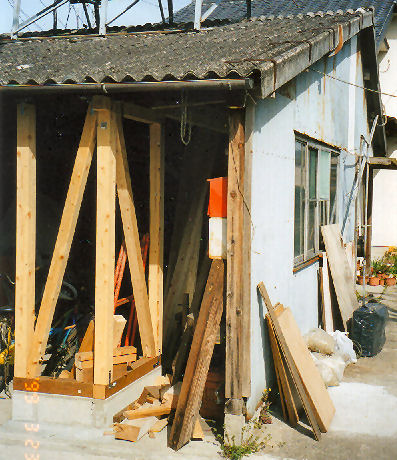
For a car to be able to get in, I had to move the southern wall about 1 meter inside.
The photo shows the foundation and pillars are done. I bought timber at a D.I.Y. shop and carried it home on my wagon(Toyota Light Ace).
-2/10-
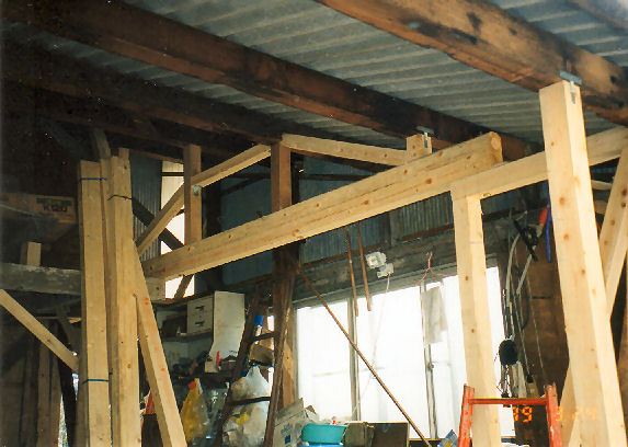
Inside fixture under renovation.
-3/10-
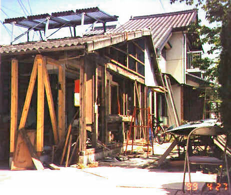
The inside fixture is finished and the southern old wall is being removed.
-4/10-
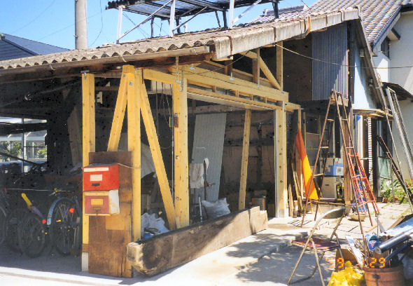
A new frontage is appearing.
-5/10-
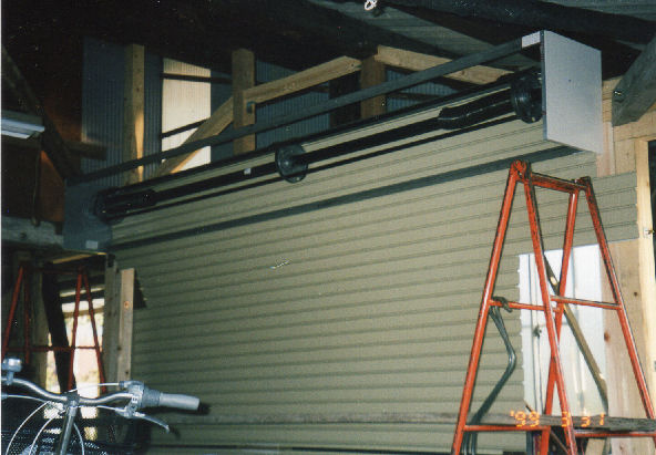
I had a shutter installed. The worker came to measure the frontage beforehand.
An electric apparatus for opening and closing the shutter was too expensive for me to buy then. Now, as I got older and find it rather hard to open it, I want it.
-6/10-
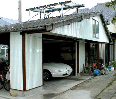
The new completed frontage of the garage.
The nose of Mazda Miata, the car I owned then is parked inside.
Miata is gone and the garage is now my workshop. My wife's car, which took place of Miata, is parked outdoor.
After completion, I had the front of the garage concreted.
-7/10-
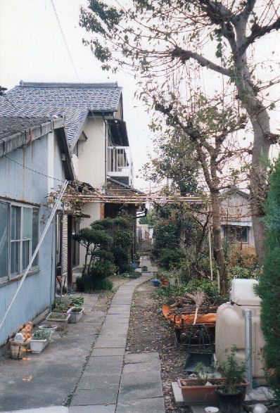
The photo of the garage before remodeling. There was not an enough space then.
-8/10-
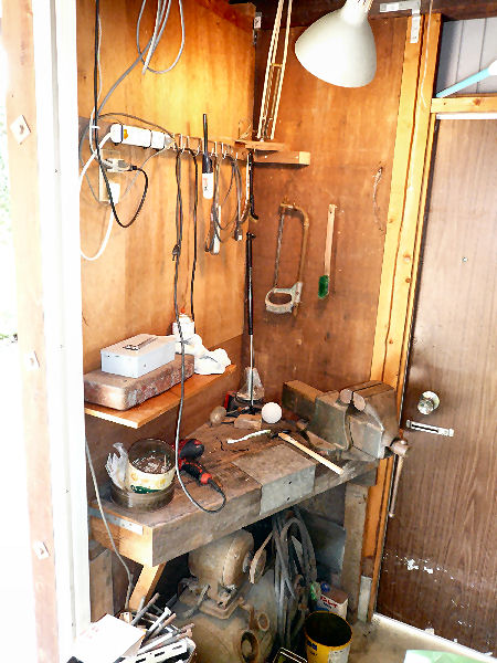
I made a workbench at a corner.
There are a vise on a thick heavby bench and an air compressor underneath. Regrettably, the place by and by lost its function stuffed with things.
-9/10-

-10/10-
Return to the listPainting Of Eaves
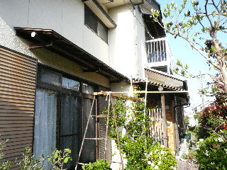
I repainted the eaves that had not been taken care of at all since the house was built. I repainted the two eaves on the southern side of the house as I happened to find them partially rusted away. It was too late to fix but I repainted them trying to prolong their lives.
I set the foothold for the first floor eaves using two step ladders and long stepping boards that I had made for working on the roof. To make the foothold safe, I connencted it with a long pole to the tree nearby.
-1/13-
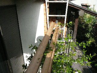
Top view of the foothold.
It had no rails and so you had to walk or work on it leaning against the edge of eaves or grabing it with your hand.
Ii is better, of course, for an older man like me to install a safer foothold, but building such foothold needs much more energy and time. Thus my work is adventurous each time.
-2/13-
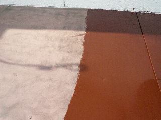
You need to remove the rust before painting.
Removing the rust is tiresome and takes much more time and energy than painting.
-3/13-
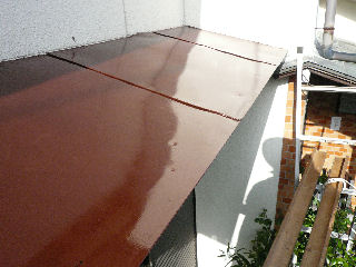
Painting done!
-4/13-
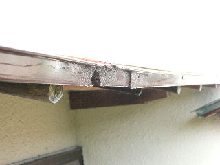
I carefully removed the rust and painted the part where tin had been rusted away. The timber around the part was also rotted off, too.
-5/13-
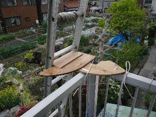
The other eaves is installed above the porch on the upper floor. There is a part on it, too, where tin had been rusted away.
I first installed a ladder catch over the rail. On the bottom of the catch were screwed wooden pieces which caught the rail tight. It worked well and I could bring up tools and stepping boards smoothly.
-6/13-
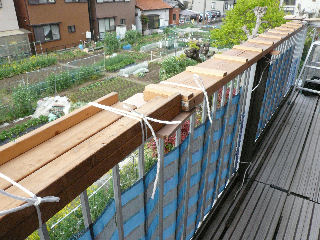
I fastened the stepping boards on to the porch rail as in the photo, installing a prop to stop the stepping board from tilting.
While installing the boards, I made a big mistake. That is, I let one stepping board fall. It struck and broke two tiles as in the next photo.
-7/13-
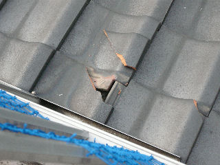
Broken tiles.
-8/13-
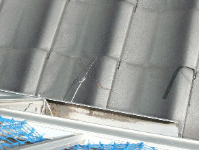
After painting, I mended the tiles as in the photo.
We had spare tiles but in replacing them with the new, you had to move other tiles around. It was not recommendable I judged. So, I mended them by glueing. The wire and black plastic tape are for holding the glued pieces tight.
-9/13-
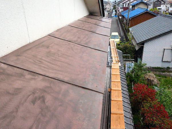
The photo shows rusting, the more tiresome and time consuming work than painting is done.
The view makes you feel you are at a much higher place than you are, which the vew from the ground never suggests.
I had to manage to operate a wire disk attached to an electric drill with one hand as I had to hold the edge of the eaves with the other all the time. The work was most difficult in the painting this time.
-10/13-
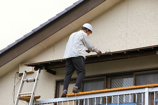
This is how I worked. I'm grabbing the edge of the eaves by my right hand in this photo.
I had it taken by my wife. It looks nothing difficult but in reality, you had to be paying attention not to step off nor let anything fall at all times
-11/13-
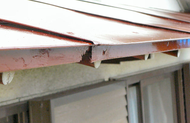
There was a similar part that rusted away on this eaves, too.
Again, I carefully rusted off and painted, wishing it to survive as longer.
-12/13-

Done!
Not to damage the painted surface, I started painting from the right end to the left, without stopping on the way, finally getting down from the foothold holding the ladder. Newly painted surface is beautiful.
I only wish it survives longer・・・!
-13/13-
Return to the listPruning Of A Mukutree
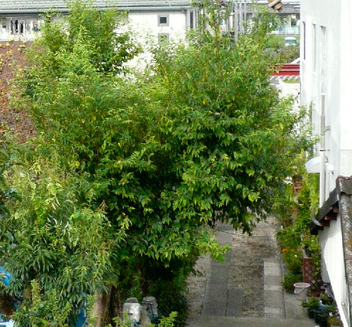
I have been pruning the trees around the house for years since retirement. Well, we have a big mukutree which has been providing us with a wonderful green shade.(The photo was taken in June.)
However, it grew very big(tall) and I had found it too hard for me to prune the tree last time.
I recognized I had only a few years left before I must stop climbing the tree, and I made up my mind to cut the tree shorter.
Pruning trees brings you a lot of branches to dispose of and you need a few days to finish everything. So, I scheduled the days of pruning consulting with the wether forcast.
-1/7-
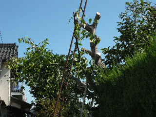
This is the tree after pruning.
I pruned the tree in such a way it won't spread branches in higher position and over the neighbor's land. I refrained from cutting the whole upper trunk as I surmised it too dangerous for me to try. I used an electric reciprocal saw in pruning, which enabled me to complete such tough work in one day.
In cutting, I connected the cutting block with a piece of plastic rope to the tree. However, once a big block, swayed wide and hit me on the ankle as it was cut off. The ankle swelled and soon turned dark blue with internal bleeding. It seemed a kind of sharing of pains between the tree and me(?).
I also made a cautionless mistake. A smaller block, which I didn't connect with rope, unexpectedly hit a branch as it fell down, jumped obliquely and it finally hit the water tank below and broke its top cover.
You must know raw wood is much heavier than it looks.
Carelessness can be very dangerous!
-2/7-
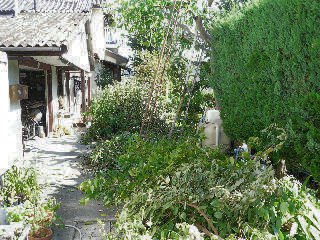
Heaps of branches and wood blocks occupied the space in front of my workshop. I left them there to be disposed of the next day trusting the weather forecast. Good weather seemed stable for a few days.
-3/7-
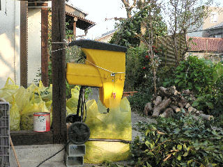
Good weather continued the next day.
All the branches and wood blocks including those of other trees were disposed of. 21 45-litter plastic bags were needed to clear the space.
Our city collects combustible garbage twice a week. Each family can bring out three garbage bags at a time. So, it took one and a half months to clear all the bags.
Big wood blocks were left outside to let them dry out to be cut smaller later.
-4/7-
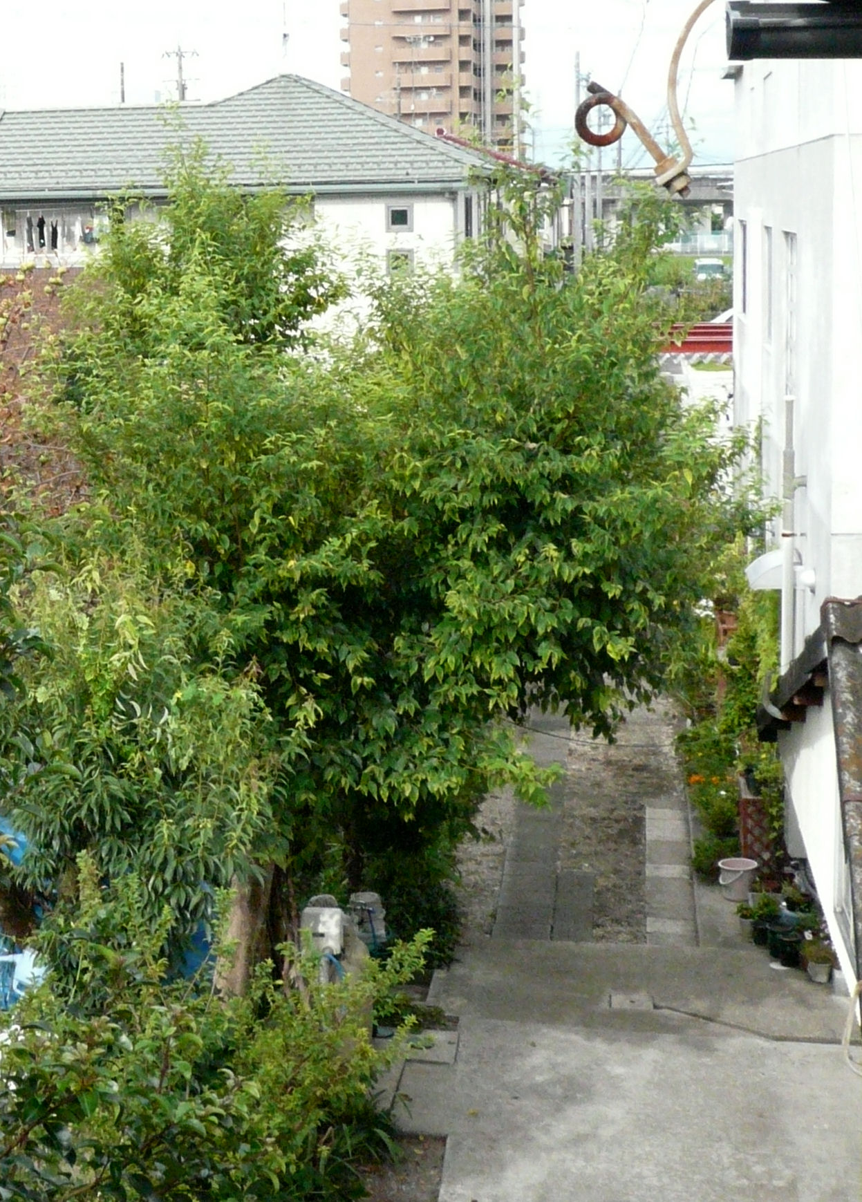
The photo shows how the tree spreaded branches the next year. They didn't grew in higher position but in lower position as in the past. Pruning in the fall looks easier, too.
-5/7-
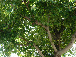
Upward View Of the Tree
It's a real green shade, isn't it? I like it very much.
-6/7-
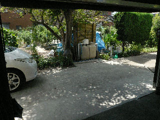
This is the view from inside my workshop/garage. The green shade is provided with just as it had been done in the past years. It cools down the inside, too.
The best place for BBQ and my work outside.
-7/7-
Return to the listBall Tap Link
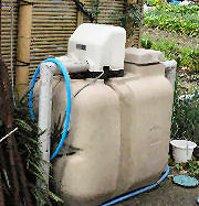
Our house when built was located on the outskirt of a village where the water pressure was lower. In order to apply more pressure, we installed a tank with a motor. The apparatus has been used many many years without any trouble.
However, one day, a meter reader pointed out that a greater volume of water had been used suddenly and had suggested us to check a leak.
She was right already twice in the past.
-1/8-
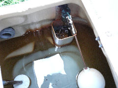
I found a ball tap link in the tank we installed had been broken and water had not been stopped tightly causing continuous overflow.
-2/8-
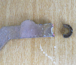
A link arm to push the valve was broken as shown in the photo. Why broken? Was the metal excessively hardedned?
Naturally, the link arm was not sold in DIY shops nearby. They sell a ball and a tap only in an assembly. So, I decided to make a copy of the link arm by myself.
-3/8-
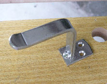
I looked for any stainless fitting out of which I could cut out the link arm and I picked up a catch for a door bolt. Both the thickness and the size were appropriate.
-4/8-
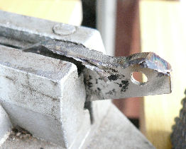
I copied the shape on the catch and scraped off with a disc sander first and finished it with a file.
-5/8-
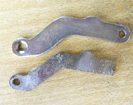
A new link arm was completed afte drilling a hole and finishing it with a fine file.
The shape is not quite the same but the relative positions of a fulcrum, the points of force and action are the same.
-5/8-
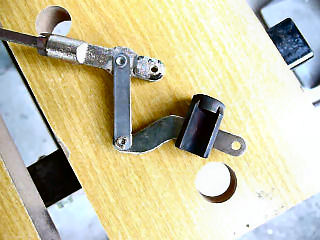
The photo shows the reassembled tap.
It was installed back to the tank and has been working right.
Incidentally, I cleaned and disinfected the inside of the tank before using.
-7/8-
-8/8-
Return to the listCracked Water Pipe
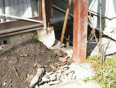
Once our meter reader pointed out that the amount of water we had used was unusually plenty.
Sometime before, we had found a leak advised by the same reader. The leak was from one of the releaf valve installed to the solar heating tank, which was above ground.
This time, the leak must have been somewhere underground. I knew no way to find it. However, one day I happened to notice a wetter place over the pipe route.
I didn't expect the point of leak was just below the wet place. But, you had to start anyway. I gouged concrete and severed out the portion around the spot.
-1/4-
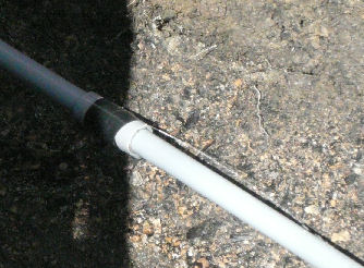
Luckily, though the leak was unlucky, I could hit the crack on the pipe. The spot was just aroung the center of the wet place. Water was coming out of the crack forming a piece of thin film.
In the photo the crack was bound with a black plastic tape to stop the water force.
-2/4-
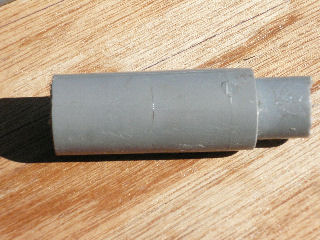
The cracked joint sleeve.
The crack bore on a joint sleave. Why on the sleeve was the question, for it was thicker than the pipe.
I closed the stop tap, cut the portion out, and installed the mending pipe with two new sockets.
In mending, to stop water and dry the pipe ends were not easy, for the water in the pipe continuted coming out little by little. It took a while before the water stopped coming out and I could dry the parts to glue well.
-3/4-
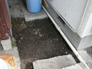
The spot refilled.
In refilling, I beat earth under the pipe to stop it as possible from shrinking down. I thought otherwise the earth over the pipe consequently press down the pipe and cause another trouble. So far, nothing seems to have happen with the mended pipe.
-4/4-
Return to the listDashboard Box Lid
Toyota Estima

One day, the pocket lid behind the steering wheel stopped responding to the release button. It stayed closed till I opened it manually. I thought the spring was broken. The ETC unit was installed in the pocket and the mal function caused a big inconvenience.
I asked my car dealer if they order the spring of the lid for me. The person in charge said no. He said it was not caused by the spring alone but by the whole assembly. That is, I had to replace it with the new. It was about 15,000yen. I thougt it was worth trying to repair it myself.
-1/6-
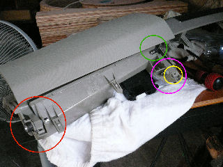
I asked the salesman through whom I bought the car the way of detaching the assemly. It was rather easy.
Later, I detached it at home and knew how it was broken.
The coil spring wasn't broken. What were broken were the axles and the parts around them(circled in red and pink in the photo).
The assembly after repair:
I installed a new metal stopper as you see it in the green circle. It is more away from the axle than the original stopper in the yellow circle, which is so close to the axle as to break it by the force charged each time I tried to open the lid too far.
-2/6-
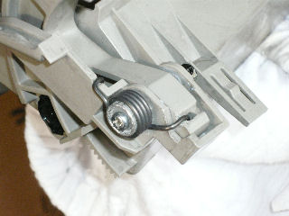
Repair processes:
① I repaired the broken plastic parts with an adhesive.
② I installed a new sleeve made with an aluminum ring. The sleeve holds the spring and is held inside the spring by an washer.
③ I assembled all the parts over a steel bolt which backs up the damaged original plastic axle.
-3/6-
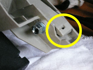
④ I did likewise on the other side.
The stopper, which is in the yellow circled, is too close to the axle as to charge it multiplied force givien to the lid of a long lever.
The plastic used to the assembly is not so strong.
SO, THE DESIGNER SHOULD HAVE PAID MORE CONSIDERATION!!
-4/6-

Close-up of the stopper I installed:
The result was not fully satistactry, like:
① The lid doesn' open as wide as it did before because of the new stopper.
② The movement of the lid is not as quick as it did before.
However, the push button revived. The mechanism seems more sturdy and durable. I would buy a new assembly next time.
-5/6-
-6/6-
Return to the list
Cleaning And Condenser Tuning Of Quartz Clock Movement
Skip to see Condenser Tuning.
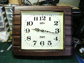
The photo shows the quartz clock in our living room. It started to get slow even with a new battery. I have had a notion that quartz clocks are expendables and they can't be repaired. So, I have never tried to repair one before. But this time, somehow I happened to think ofChecking through the pages over the internet, I learned clock movements are not expensive. They sell one for 450yen to 1300yen(for a cuckoo clock). They don't sell any special long life version. Also, they can be restored by cleaning.
The last information decided. Changing the movement with a new one can wait. repairing it.
-1/16-
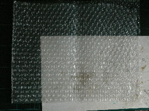
Before setting to work, I cleaned the desktop and around it to keep the movement out of dust. Also, I put a cushion sheet to protect the clock face.
The day I did the work was fortunatly rainy, a less dusty day.
-2/16-
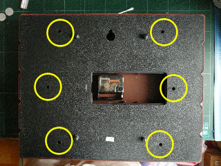
The photo shows the back side with a battery and the lid taken off.
First, I took off the back plate. It was fixed with six screws at the places marked with yellow cirlces.The holes were smaller and a slim driver was needed.
-3/16-
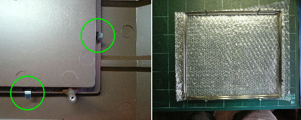
Next, I took off the glass on the face. It was fixed with an aluminum frame that had six fixing nails that were easily made straight.
Photo left: Two of the nails with green circles.
Photo right: The detached glass and frame .
-4/16-
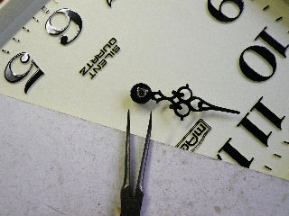
Next, I took off hands. They were inserted on to spindles and they could be pulled off, only with proper needed force. I used pliers as shown in the photo.
The hands were firmly fixed as if they were adhered. In pulling, I gave a touch of shake in order to take one off successfully. You have to be careful not ot damage the movement as well as hands.
-5/16-
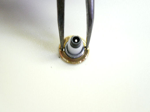
After taking off the hands, I took off the movement by turning off the nut. As I didn't have a dedicated driver, I used the same pliers I used for taking off the hands.
This time, I had to be careful not to give any scar on the clock face. One scar would have spoiled the repair even if the clock revived.
A piece of cardboard protector would have worked but I didn't make one this time. I was lazy enough to venture the repair without it.
-6/16-
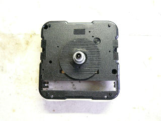
The photo is the movement detached from the clock board.
Luckily, a rubber washer was sticking the movement and the board, and the movement didn't fell when the nut was taken off. It was a luck.
-7/16-
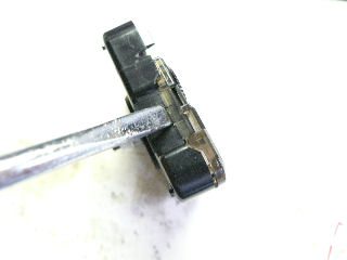
Disassembling of the movement:
I levered off the movement cover with a minus driver, applying the driver little by little on both sides in turn.
However, as the cover came off, it jumped off together with one of the cogwheels. You have to be careful not to let it happen.
-8/16-
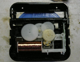
Inside of the movement.
I proceeded the work with thin plastic gloves on.
You have to note the positions of cogwheels.
You must be careful in handling them as they are very light.
-9/16-
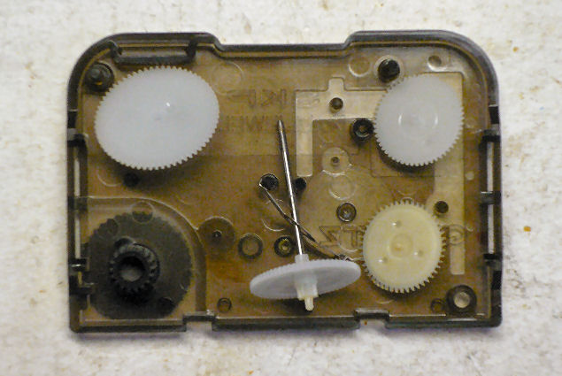
These are the cogwheels that were taken off and put in the movement cover.
-10/16-
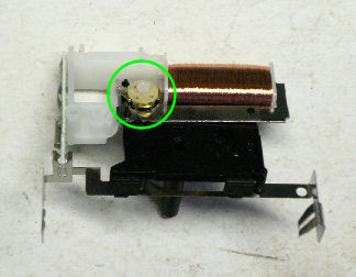
After taking off cogwheels, I took off this component from the movement case.
The component is the engine of the clock consisting of a driving coil and a rotor(green circled).
The rotor is very small and easy to be lost.
So far are the processes of disassembling.
-11/16-
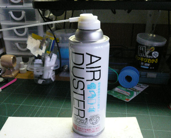
Cleaning:
I used a spray duster as shown in the photo. You apply jet air on to each cogwheel and bearing.
You may not find any difference after cleaning.
After cleaning, I assembled the movement again. In this occasion, I could proceed assembling very smoothly.
-12/16-
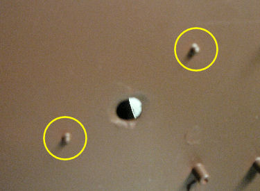
As I put back the movement on to the clock board, the guides(yellow circled) helped me. You can't make a mistake.
-13/16-
-14/16-
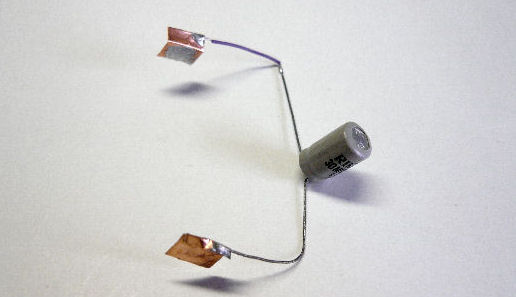
Condenser Tuning
So I did the condenser tuning with installing a chemical condenser attachment as shown in the photo. The condenser I was of 30MF/10V. It hppened to be at hand.
-15/16-
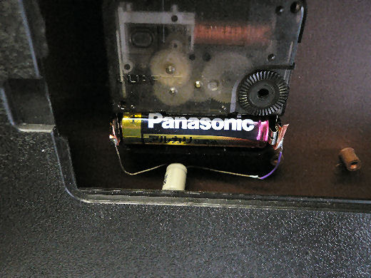
I installed the attachment as shown in the pnoto. How did it turn out? The clock revived!
It seems that the energy stored in the condenser supplies the needed energy quickly enough which the battery is unable to respond. This method can be an alternative of one more battery to be connected parallel I thought.
-16の16-
Supplemet:Movement replaced
(Installed on 2019/05/14)
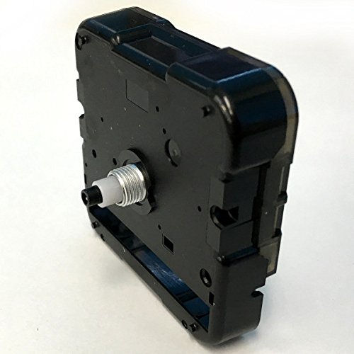
The clock finally stopped dead and I replaced the movement with a new one at last. It started again with the trial battery that came with the movement.
The photo shows the one I bought through Amazon. It's a Kishizuka Kikai made short-shafted sweep moving type movement. I could install old hands OK. The price was ¥1306 plus ¥360 carriage. The price rose during two years and 8 months after I repaired it first.
―Supplement―
Retractable Wheels
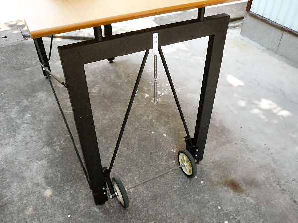
I brought the desk home from one of my son's apartment when he graduated from university.
It happened to be the time I opened my workshop and I reformed it into my workdesk. The legs are steel and the board is made of thick particle board. That is, the desk is heavy.
-1/2-
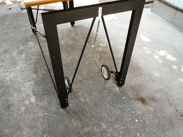
I wanted to make it movable and so I installed wheels as shown in the photos.
To use the wheels, you pull them down to outside the leggs.
When the wheels are not needed, they can be retracted inside to be pulled upward by a spring.
-2/2-
Return to the listSmall Shovel
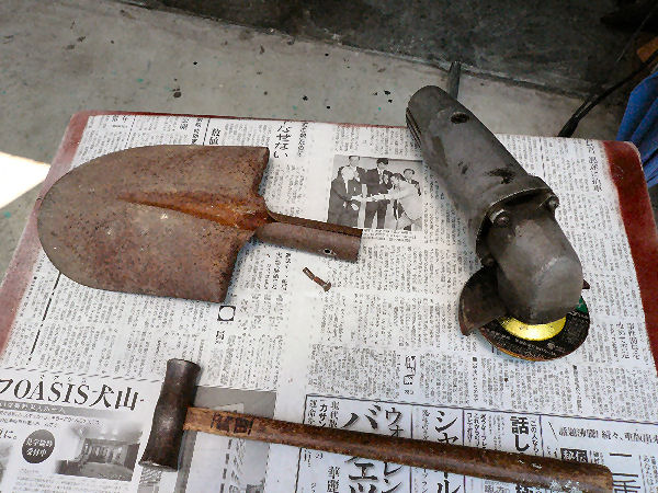
A handle of a small, convenient shovel which you can use by one hand broke.
We realized it was "convenient" as we knew we couldn't use it any more. It had been treated not with care at all. It had been left outside and got wet when it rained.
We knew we needed it and I mended it.
-1/5-
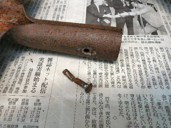
First, you have to take out the fix pin and clear the mount. I scraped off the pin head and tried to hammer it out. Somehow,it didn't come out easily. It was broken when I finally took it out.
-2/5-
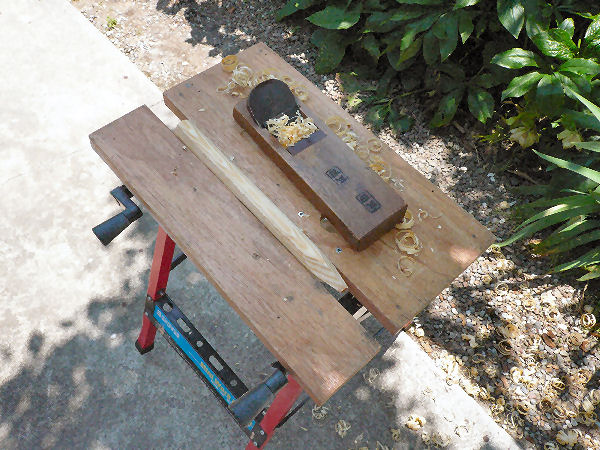
I used a piece of wood stick for a new handle, making it round by a plane.
-3/5-
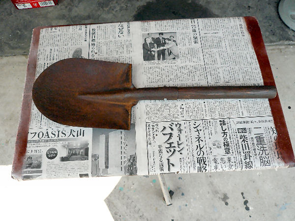
Front side of the finished shovel.
I painted the handle with paint that contained preservative.
-4/5-
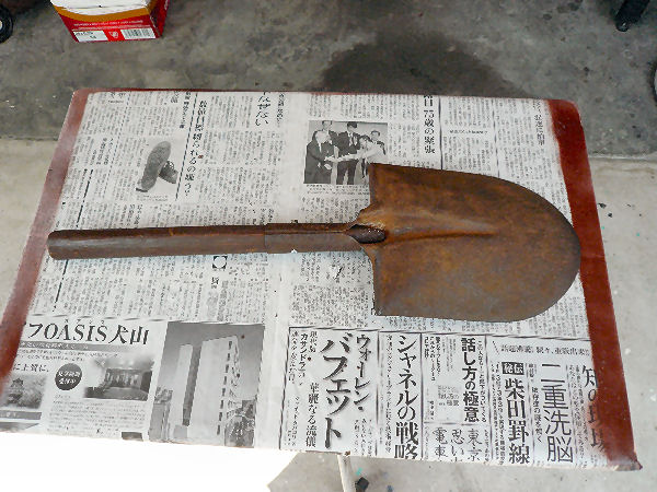
Back side.
I removed the rust in token of our thankfulness for its past contribution.
It has been kept inside since.
-5/5-
Return to the listRestoring Termite Damage
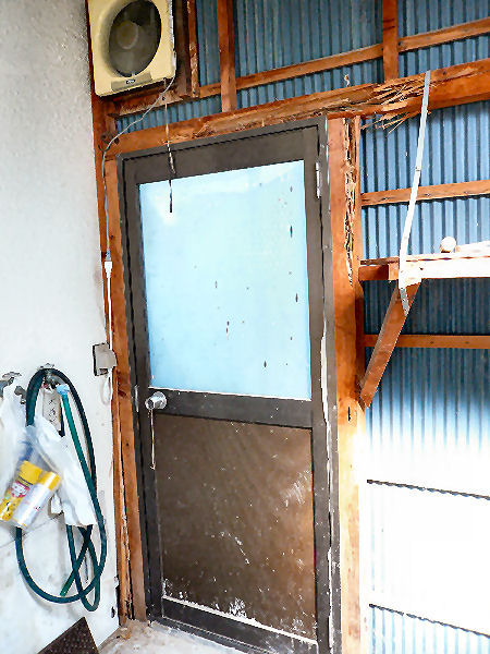
Accidentally I found termite damage around the door in our storage shed. Lucky was it that I could find it?
The restoring work took about three weeks. I had been engaged in a project then but stopped it and gave the highest priority on the restoring work.
The most difficult and hard work was to clear the place. The shed was full of things thrown in there during some thirty years in the past. They were the things almost all unnecessary but difficult for you to discard.
―1/6―
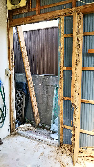
The photo shows the whole damage.
I decided to replace pillars and a beam without removing the galvanized iron sheets, which I surmised will make the work more awkward though.
Luckily, the main function of the pillars were for holding the door. They were almost free of load.
―2/6―
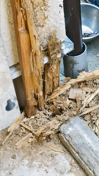
The photo is a close-up view of one of the pillar bases. They were being installed buried into the ground a little.
―3/6―
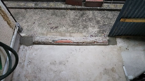
I filled the old pillar holes with concrete planning to install new pillars to be fixed with metal plates anchored onto the concrete floor.
―4/6―
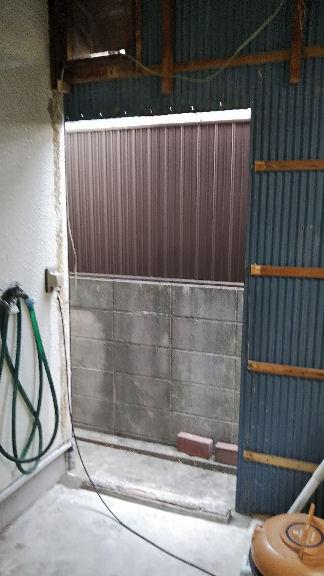
The photo shwos the place ready to be restored with the concrete filling hardened enough.
While waiting for the concrete to harden, I shopped timber for pillars and a beam. I wanted rectangular timber of 87mm by 87mm in thickness but they sell only those of 90mm by 90mm. I had to plane them thinner by 3mm.
On top of it I had to buy two 3 meter long timber for 1900mm long pillars.
―5/6―
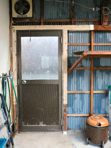
The damage restored.
In finishing the work I painted the galvanized iron sheet around the door anew and gave preservatives to the foot of pillars.
I had been poor in measuring, and so I paid a very careful attention this time that I could fit the pillars and the beam just into their places.
―6/6―
Return to the listBBQ Brazier
I brougt it back from USA in 1988.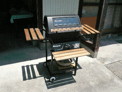
-1/2-
-2/2-
Return to the listGarden Table
A Training Piece Of My Woodwork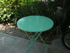
I made this round table top in order to train how to cut a wooden board into a round piece and how to paint it beautifully.
Originally, the top was plastic. It was not one piece but was composed of several narrow plastic planks which wore to tattered.
The table came to us with two matching chairs but one of them I disposed of. It was not worth repairing.
I challenged to cut out the round table top with a saw, a plane, a file and sandpaper.
Painting was a challenge, too. I painted it with a brush, which, naturally, I couldn't finish at one try. I tried three times, or I compromised with the third finish. Painting with a brush is so difficult, I learned.
It turned out to become a good match for a coffee break in the shade of a tree.
-1/1-
Return to the listMending Of Pruning Shears
(Installed on 2018/07/31)
The photo shows two pruning shears I mended this time.

I had postponed the mending for three years but using them with energy and strength more than needed came to the limit. I got older and couldn't waste my precious strength any more. So I tried the mending at last.
―1/8―
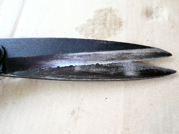
The bigger one had nicks as you can see them. I don't remember when and how I caused them. Some of them are very big but I judged I can make them well cutting shears again practically.
―2/8―
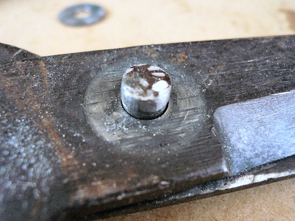
The first step of mending is dismantling but the pivot is a rivet, not a threaded bolt to be tightened with a nut. It is troublesome.
I planned to use the rivet again and so I grinded and filed the hammer crushed head of the rivets as shown in the photo.
―3/8―
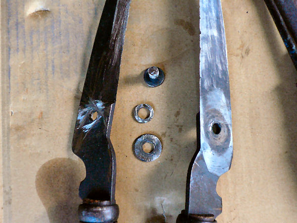
In about an hour the shears were dismantled as shown in the photo. It shows the bigger one. I sweated a lot with the work.
―4/8―
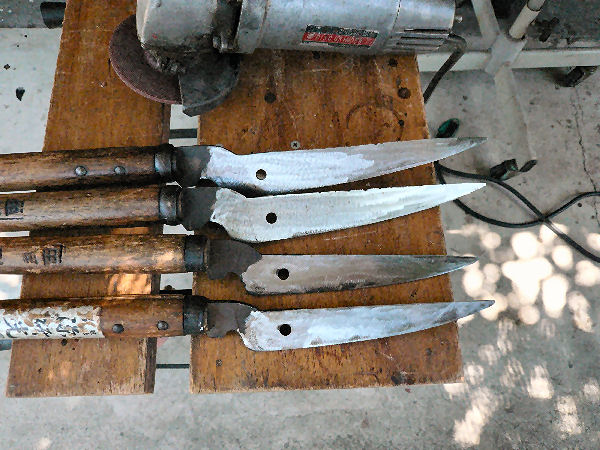
For mending the blades I used disk grinder. It is a very appropriate tool for the work because it can make a concave line as you apply it onto the surface at a small angle.
You can glind the inner surface of a blade so that the center of it becomes slightly sunken along its length but you must be careful not to grind the edge for the next process.
―5/8―
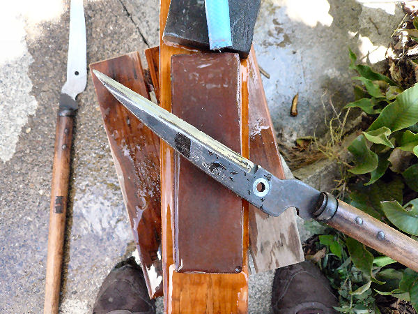
Grinding work finished you whet blades in order to make smooth and sharp edges.
With me, the work was familiar as I had experienced with chisels and planes.
―6/8―
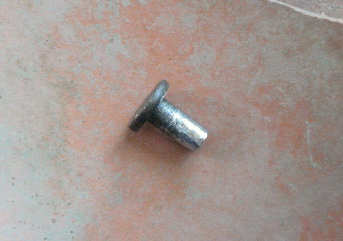
The final process is putting blades together again.
The photo shows a rivet placed on a broken piece of an earthenware.
You heat it with a hand burner and set it into the pivot holes to be hammer crashed.
The work must be done quickly and neatly while the rivet is hot. That is, I had no chance of taking a photo of this final process.
―7/8―

The mending of two shears were finished. Crushed heads of rivets look not large enough but they are practically strong enough to keep blades together.
The spring washer on the bigger shears is new as I had damaged the original one when dismantling it.
I'm looking forward to the next pruning chance.
―8/8―
Return to page top Return to the listRestoring A Septic Tank Hatch
Installed on 2019/06/20The cast iron hatch of our septic tank had dangerously corroded. I restored it as shown in the photo.
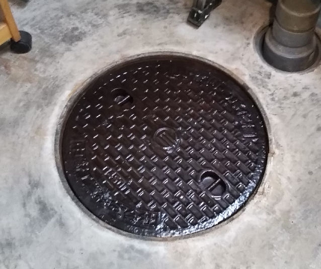
The price of a new hatch, which was too expensive, decided me to restore it with the leftover FRP materials I had kept since the last speaker making.
The hatch above looks wet but it's not. It only looks so with its polyester coating.
―1/6―
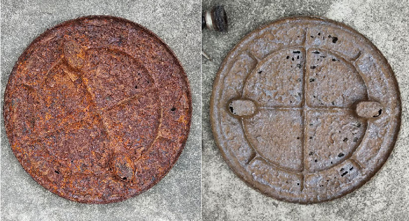
The photos show the back sides of the hatch. Left:before removing the rust. Right:after removing the rust. The hatch had grown very thin. Ignorance is bliss! We were stepping on the hatch.
―2/6―
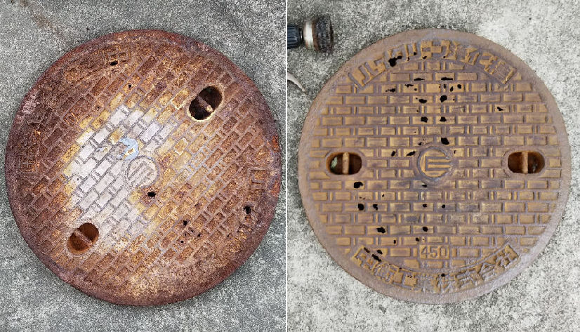
The photos show the faces of the hatch. Left:before removing the rust. Right:after removing the rust. Removing the rust was a good one day work.
―3/6―

Tools and materials used for the FRP handiwork: they are (from left to right) a paper cup, a syringe, a brush, curing agent, scissors, glass wool and resin. Repeating a step of mixing 1cc curing agent with 100cc resin(liquid polyester) is my way.
The whole surfaces of the hatch were applied with paraffin contained resin in finishing.
―4/6―
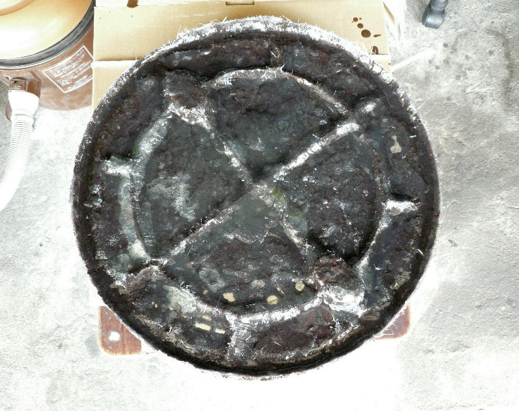
The photo shows the back side of the hatch which is covered with FRP layer. Pieces of glass wool through which polyester permeated forms the layer.
―5/6―
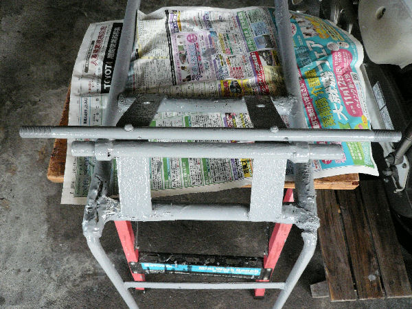
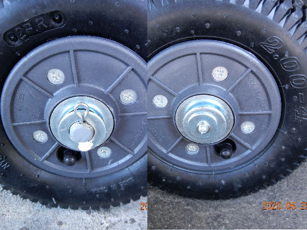
Restoring A Two-wheel Push Cart
(Installed on 2020/06/30)
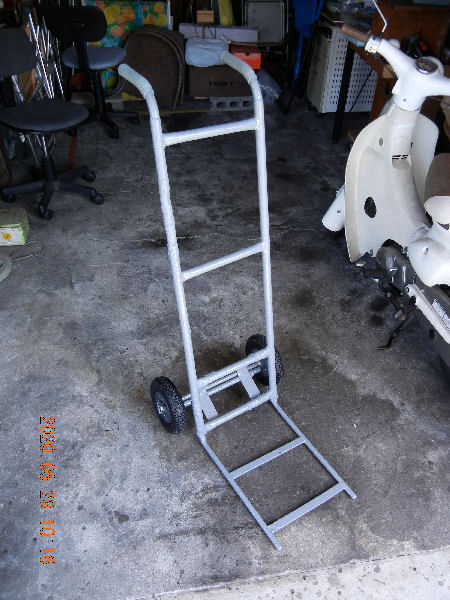
―1/5―
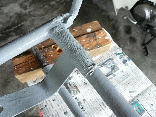
―2/5―
―3/5―
―4/5―
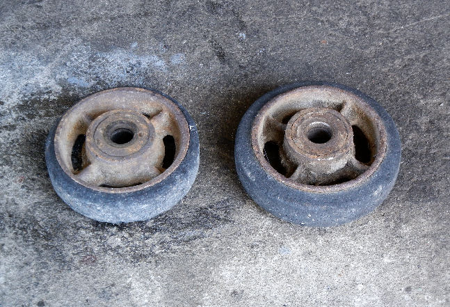
These are the old wheels. The rubber tires hardened and were worn away utterly losing their elasticity. They caused big rattle. The new wheels, I expect, are tube tires and much calm.
―5/5―
return to the list
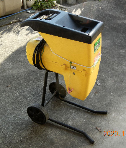
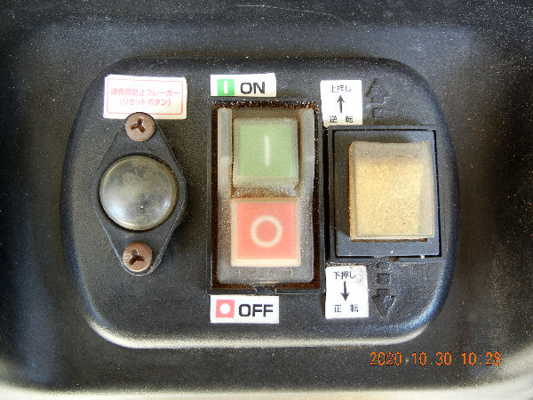
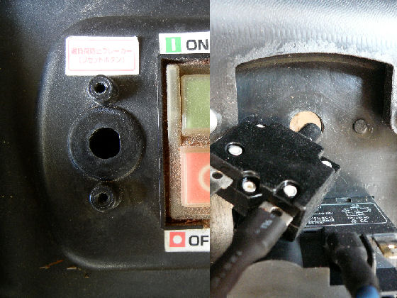
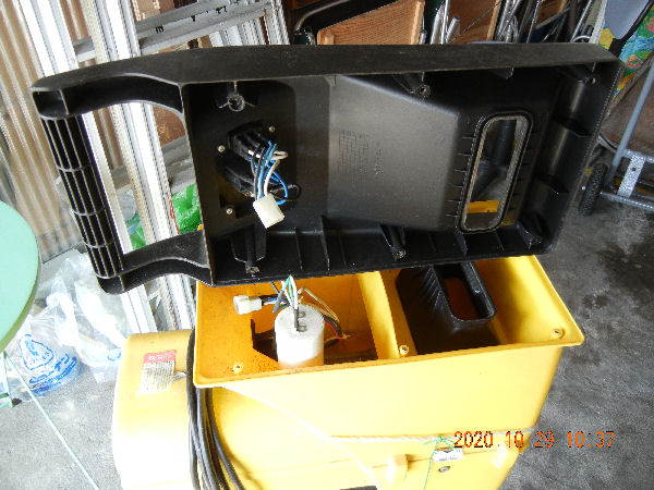
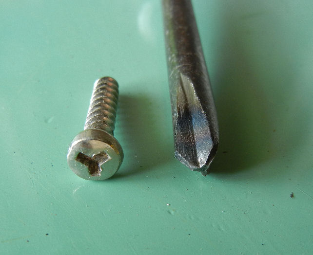
Lopped Branch Shredder Maintenance
(Installed on 2020/10/30)
―1/8―
―2/8―
―3/8―
―4/8―
―5/8―
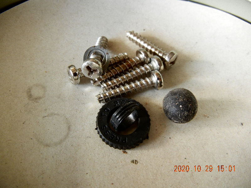
―6/8―
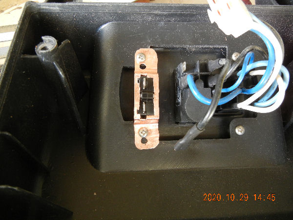
―7/8―
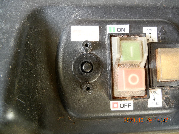
―8/8―
Return to the list.Fixing The Oven Door Glass.
(Installed on 2021/01/25)
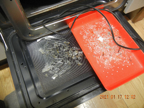
―1/7―
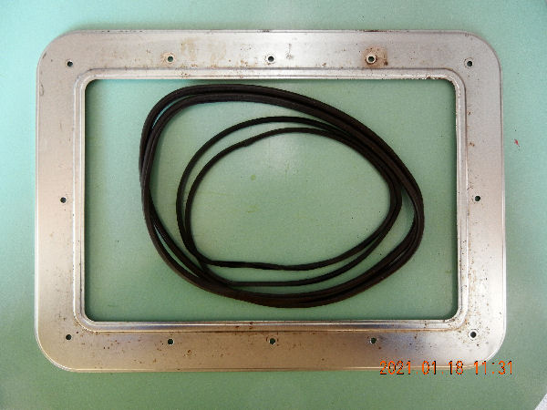
―2/7―
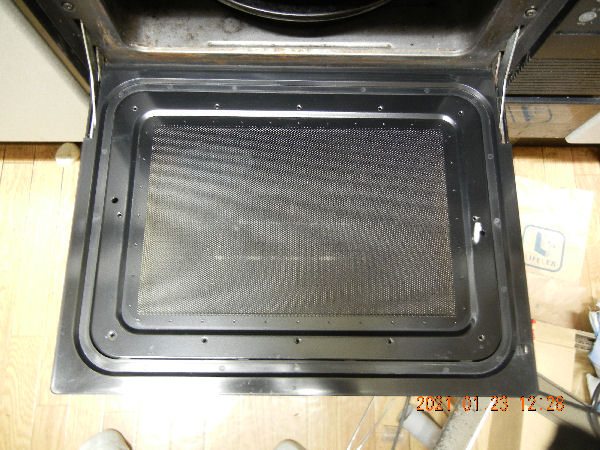
―3/7―
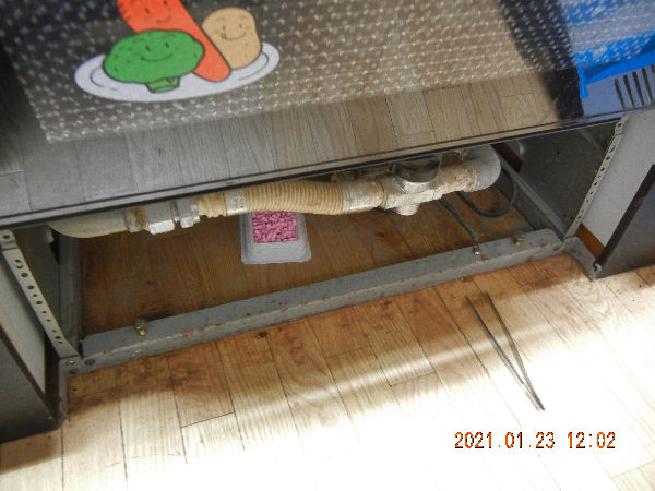
―4/7―
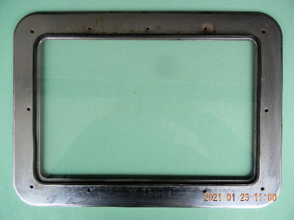
―5/7―
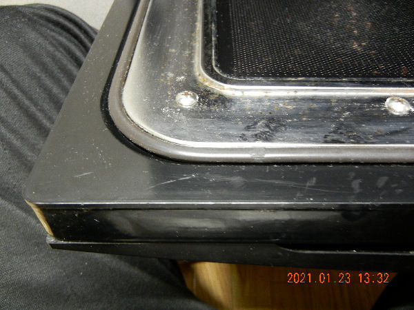
―6/7―
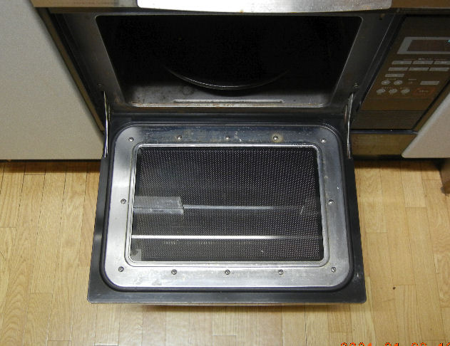
―7/7―
Return to the list.
Fixing A Shower Hose
(Installed on 2021/05/26)
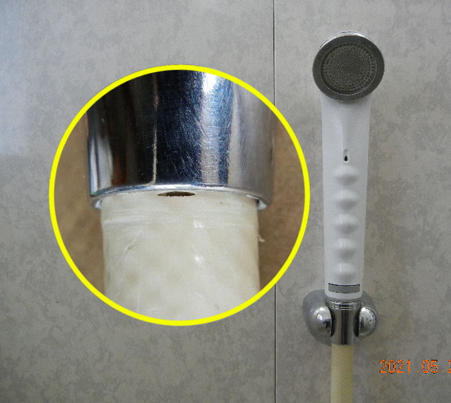
―1/4―
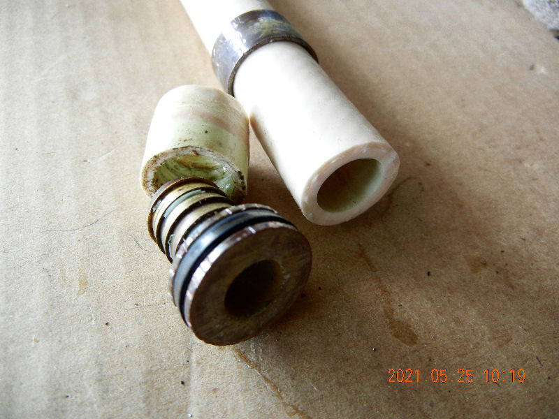
―2/4―
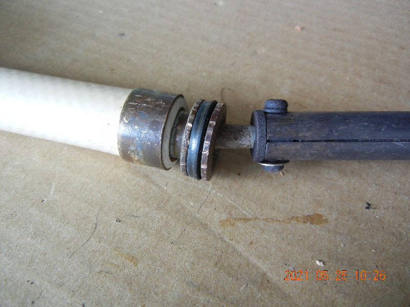
―3/4―
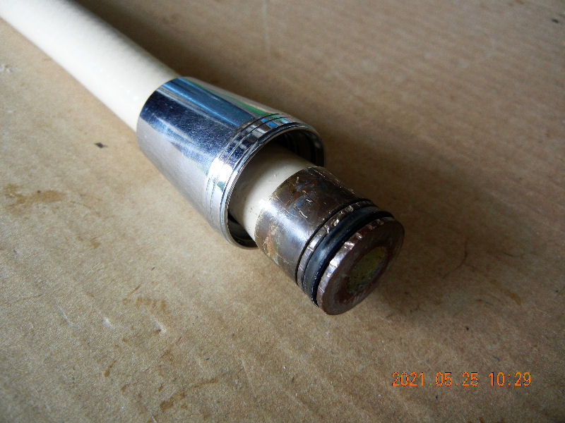
A Shutters Pull
(Installed on 2021/06/04)
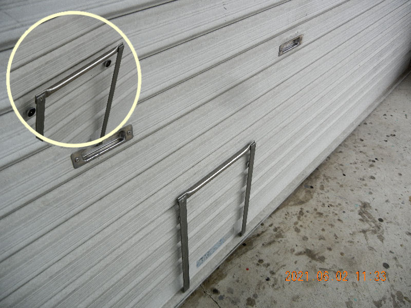
―1/3―
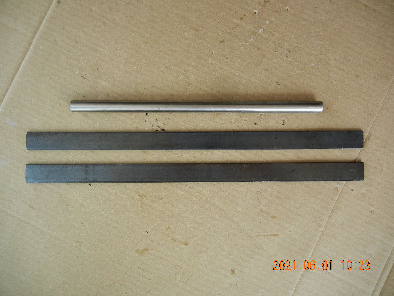
―2/3―
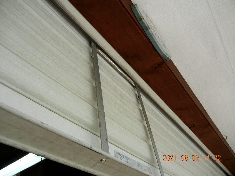
―3/3―
Return to the list.
An Under-stairs Safty Bar
(Installed on 2021/06/15)
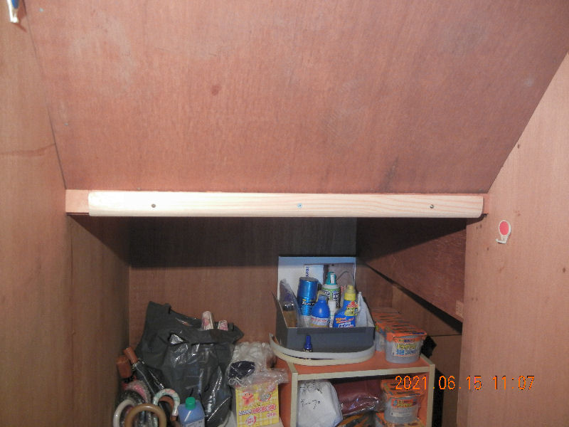
―1/3―
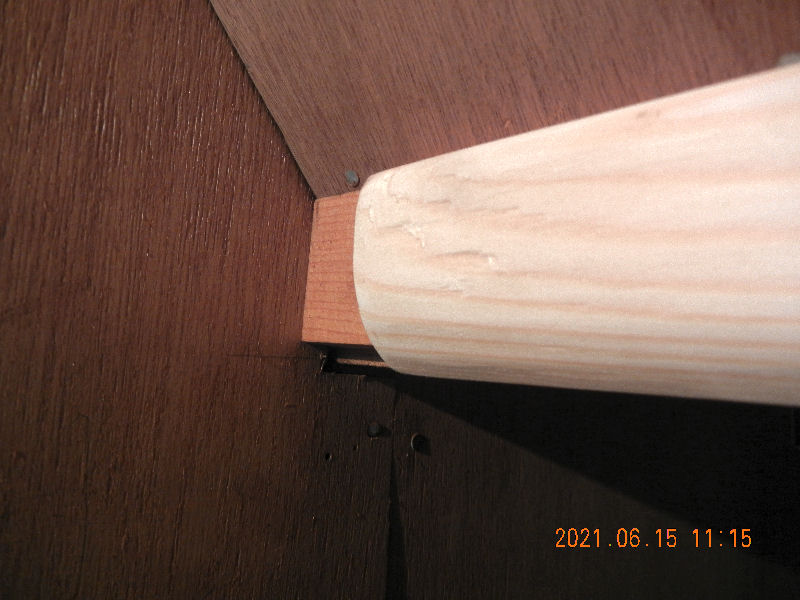
―2/3―
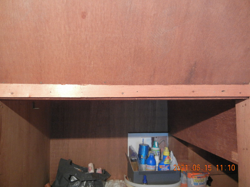
―3/3―
Return to the list.
Fixing A Rake Shaft
(Installed on 2022/05/21)
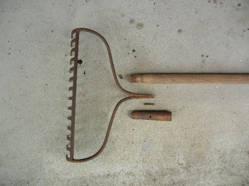
―1/5―
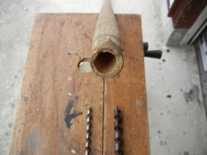
―2/5―
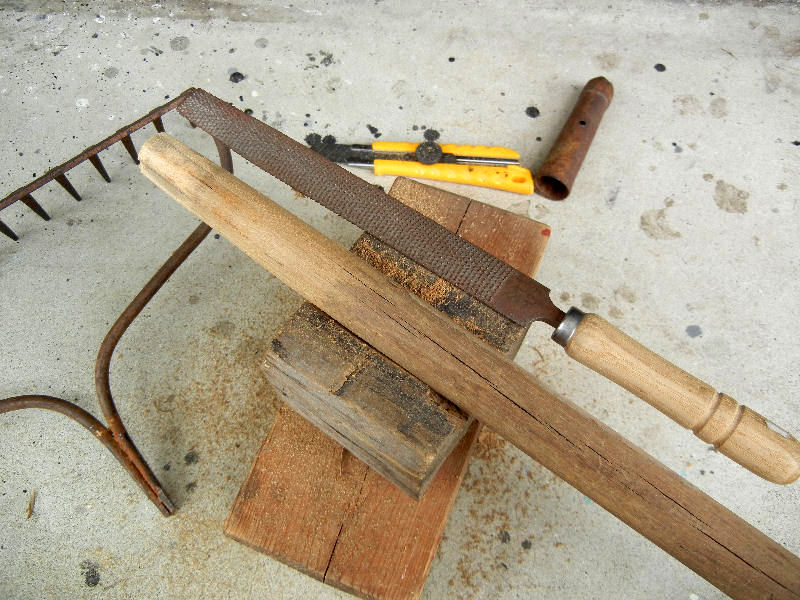
―3/5―
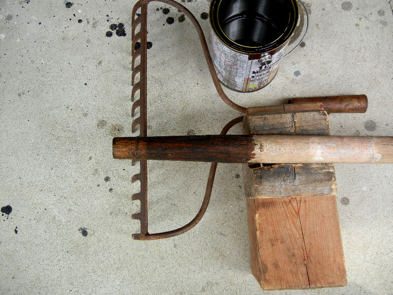
―4/5―
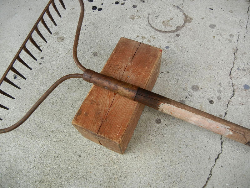
―5/5―
Returan to the list.
Attending My Handy Pruning Shears
(Installed on 2022/07/29)
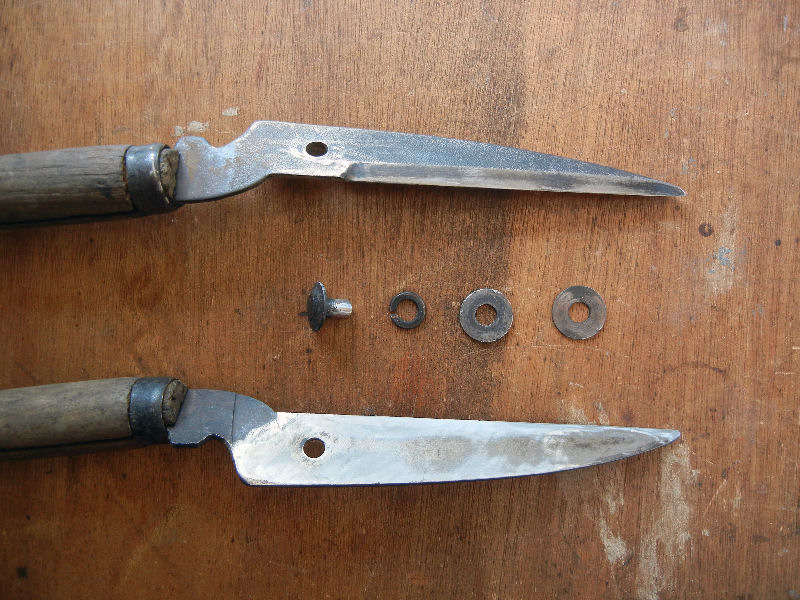
―1/4―
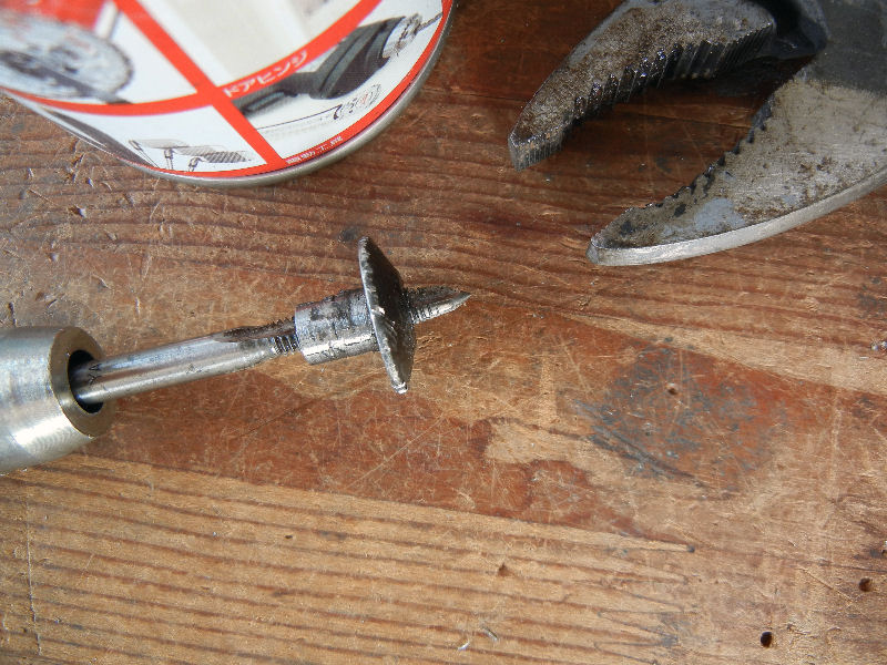
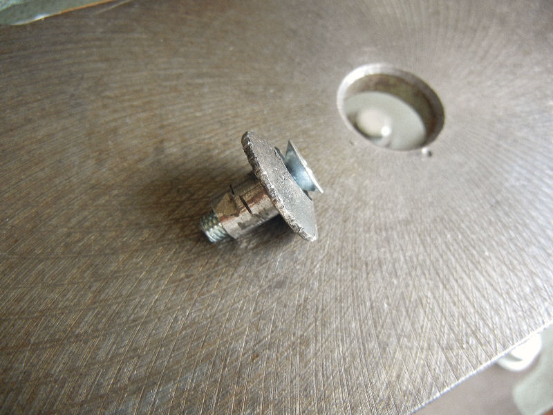
―3/4―
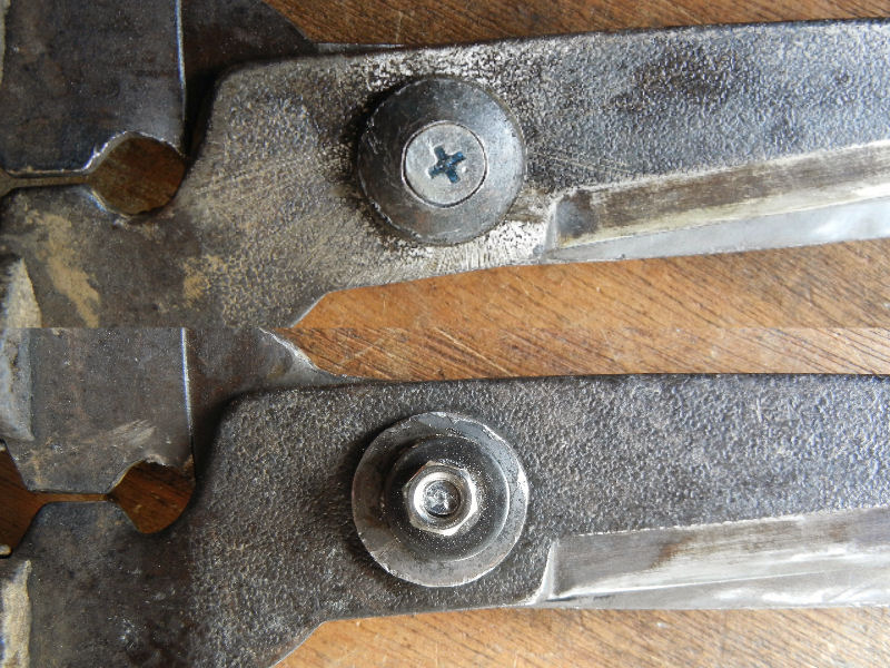
―4/4―
Return to the list.
Repairing A Side Table
(Installed on 2023/01/08)
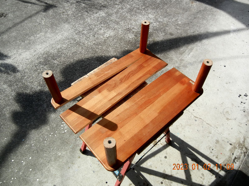
―1/8―
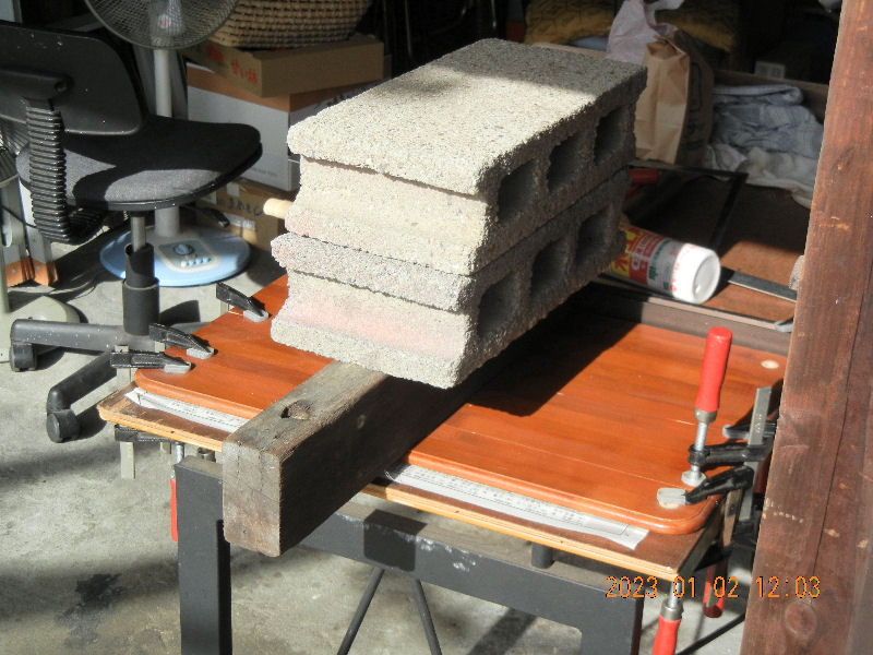
―2/8―
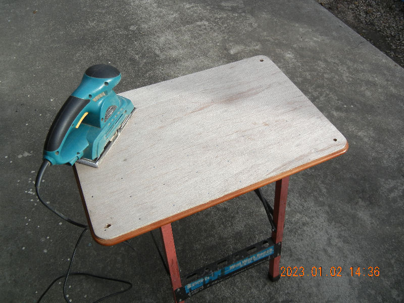
―3/8―
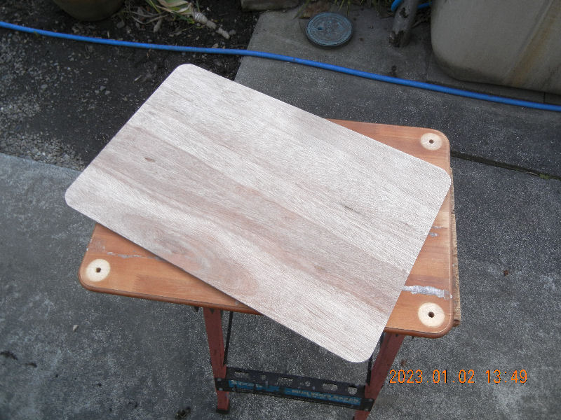
―4/8―
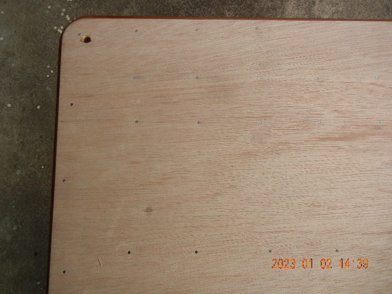
―5/8―
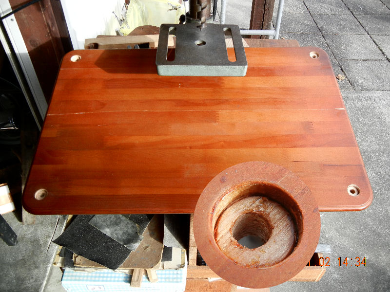
―6/8―
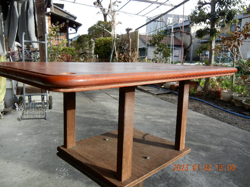
―7/8―
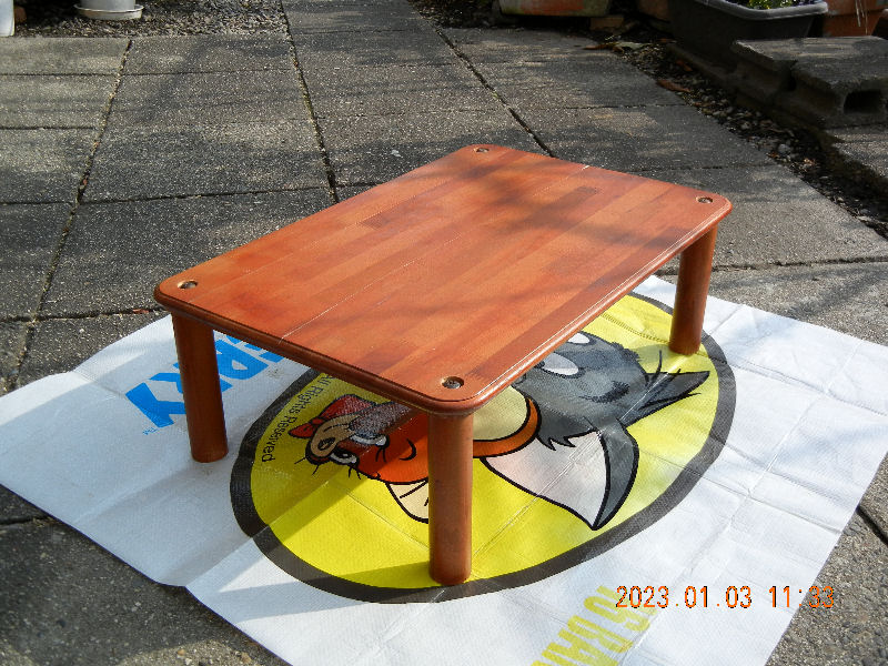
―8/8―
Return to the list
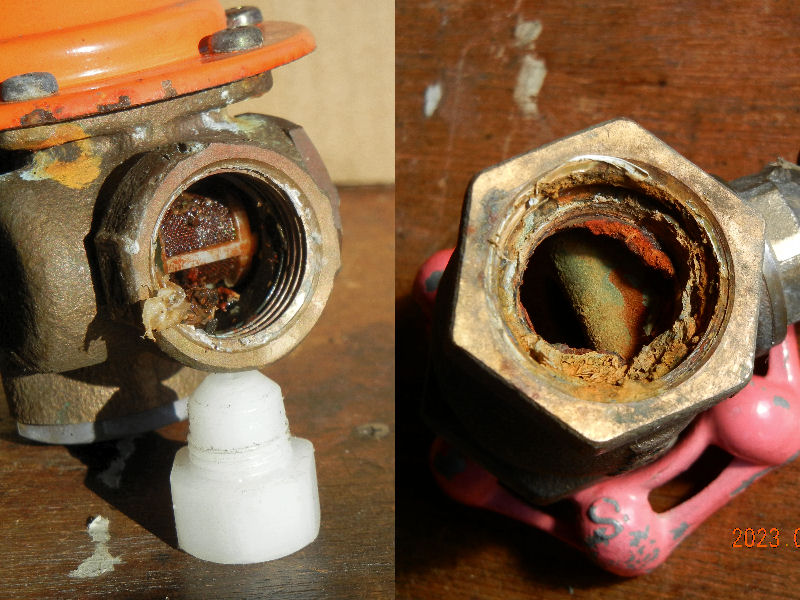
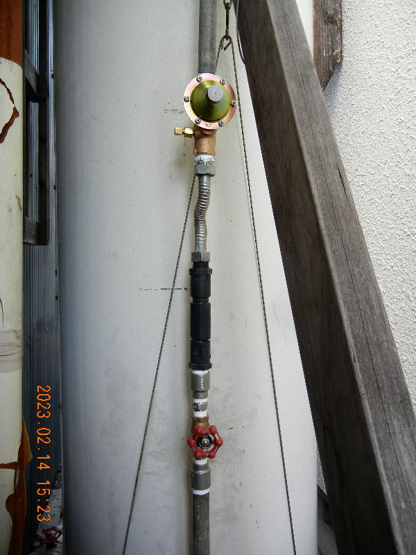
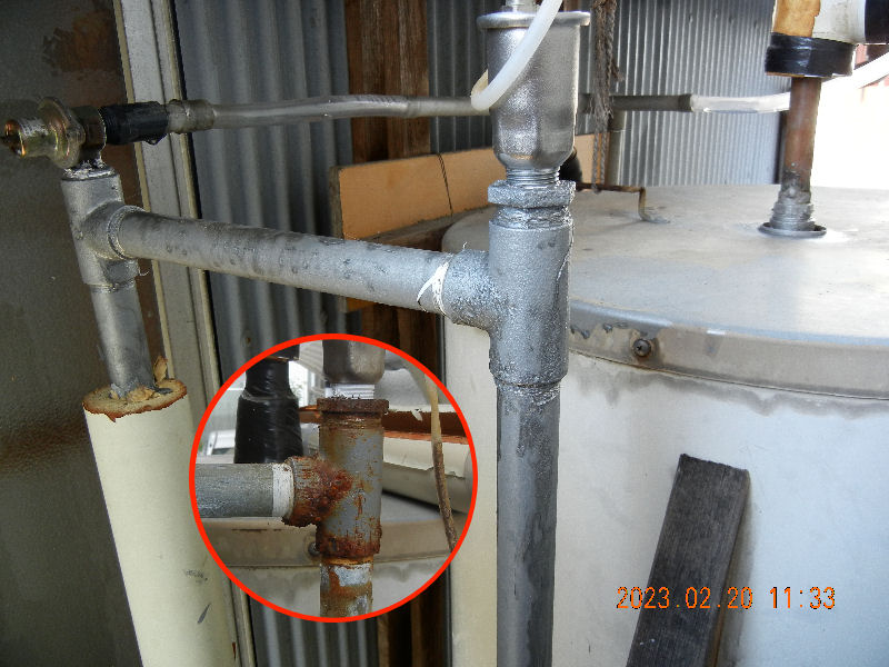
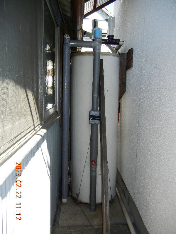
Repairing The Solar Water Heater
(Installed on 2023/02/24)
'Inlet Relief Vulve Replacement' is added on 2023/06/21
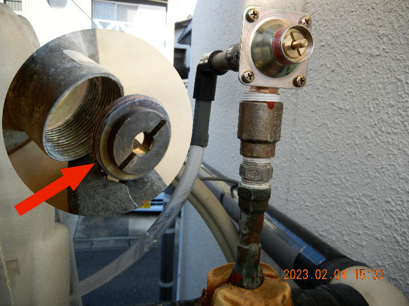
―1/6―
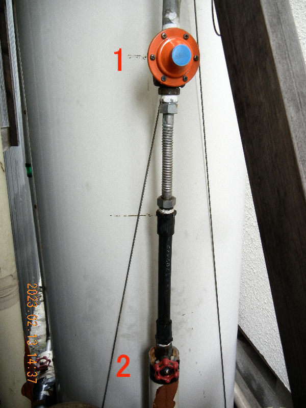
―2/6―
―3/6―
―4/6―
―5/6―
―6/6―
Inlet Relief Vulve Replacement
(Added on 2023/06/21)
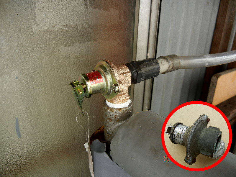
―Addition1/1―
Return to the list
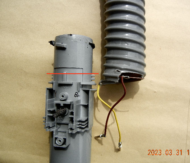
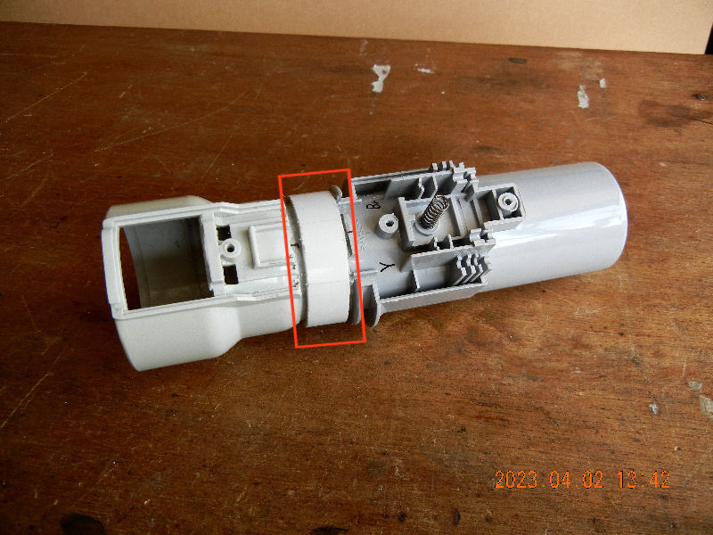
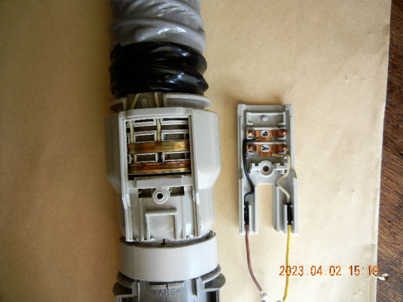
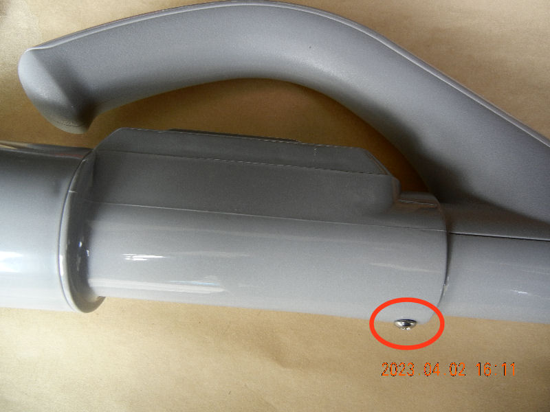
Improving A Cleaner Hose
(Installed on 2023/04/04)
Installing A New Power Switch On The Grip is added。(2023/06/13)
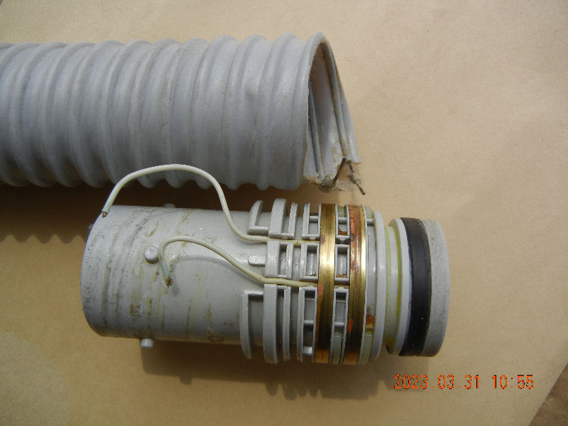
―1/8―
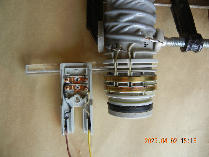
―2/8―
―3/8―
―4/8―
―5/8―
―6/8―
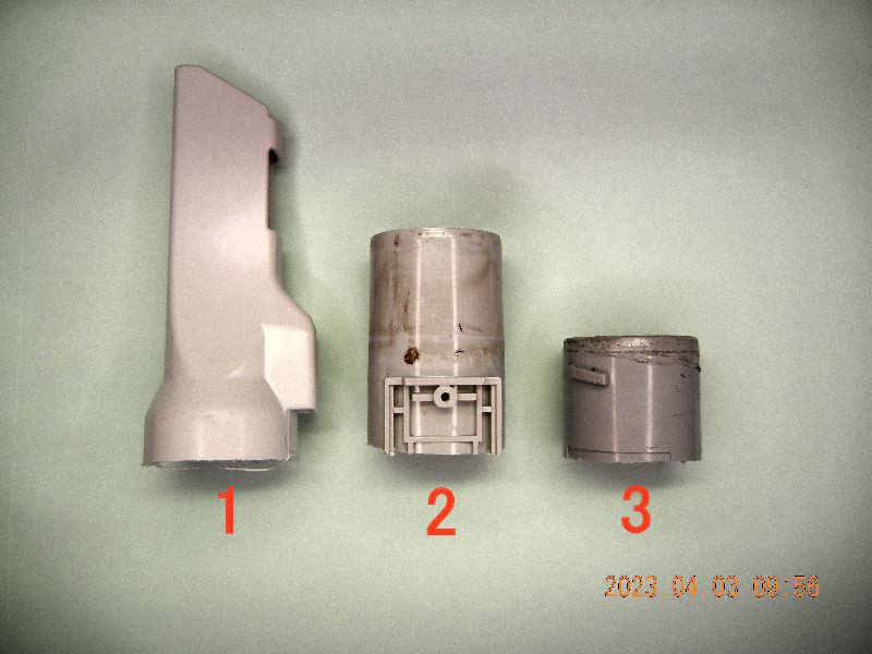
―7/8―
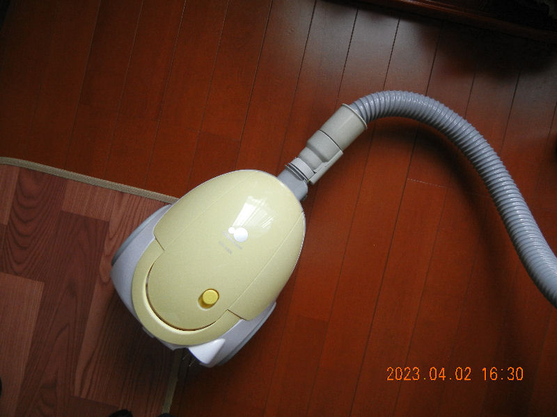
―8/8―
一覧に戻る
A New Power Switch On The Grip
(Installed on 2023/06/13)
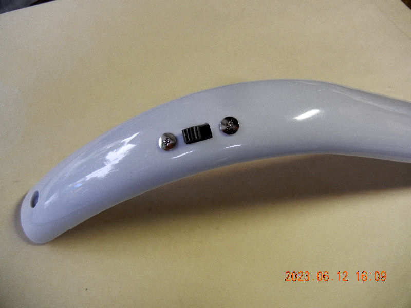
―addition1/6―
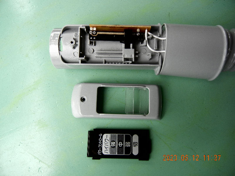
―addition2/6―
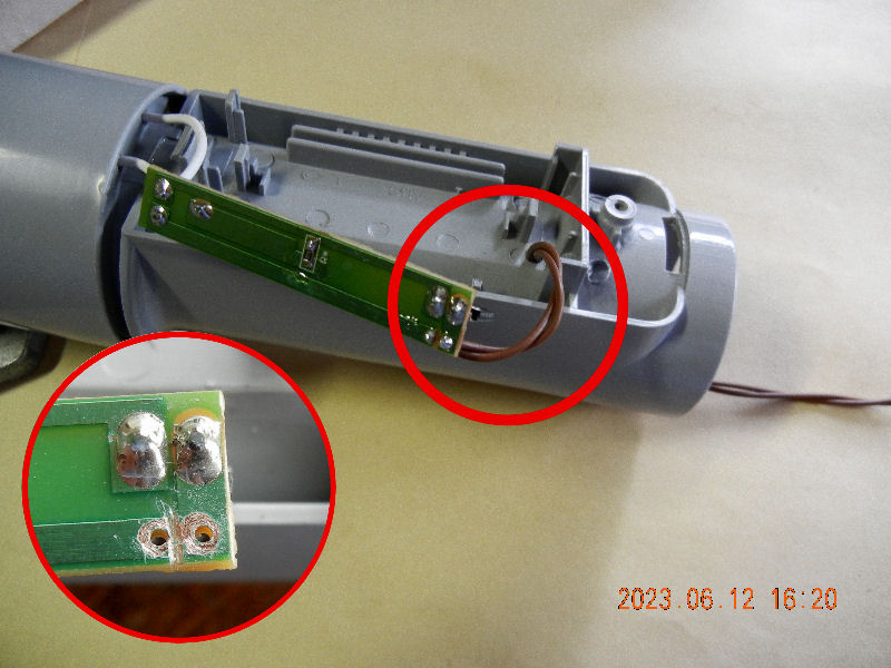
―addition3/6―
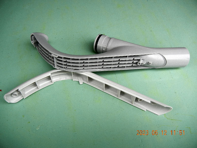
―addition4/6―

―addition5/6―
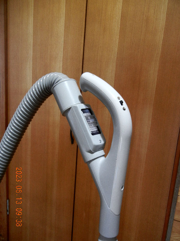
―addition6/6―
Return to the list
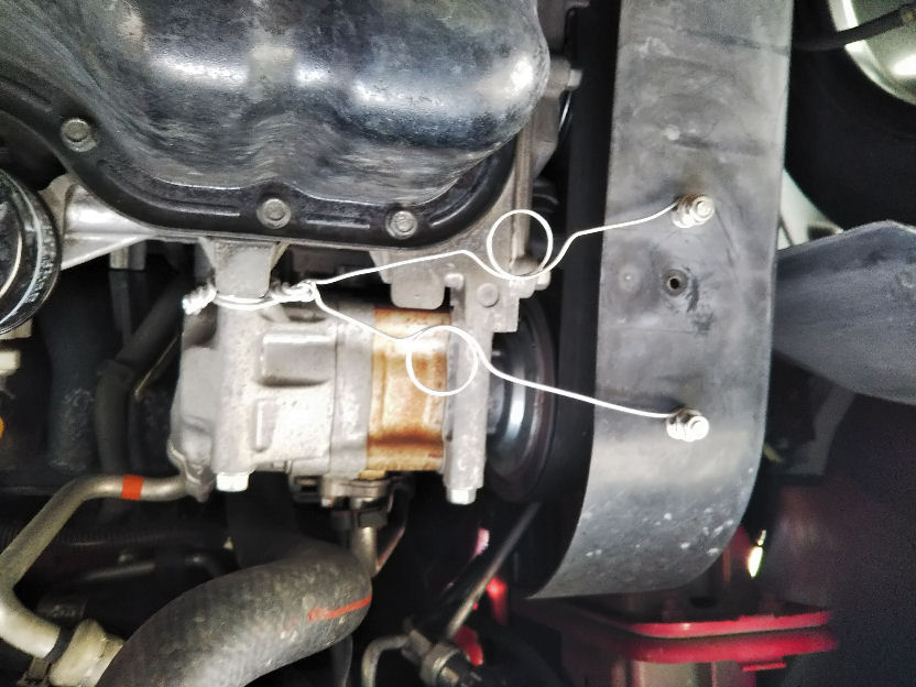
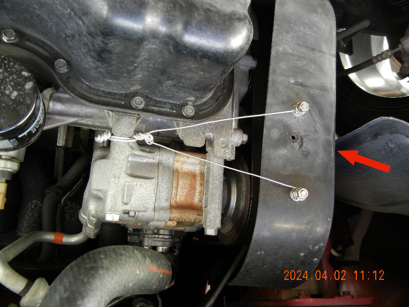
Installing A Vibration Damper On Verisa
(Installed on 2024/04/04)
I workded under the car after many years. Slipping into and coming out from under the car repeatedly wasn't such hard work when young.
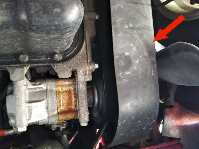
―1/3―
―2/3―
―3/3―
Return to the list
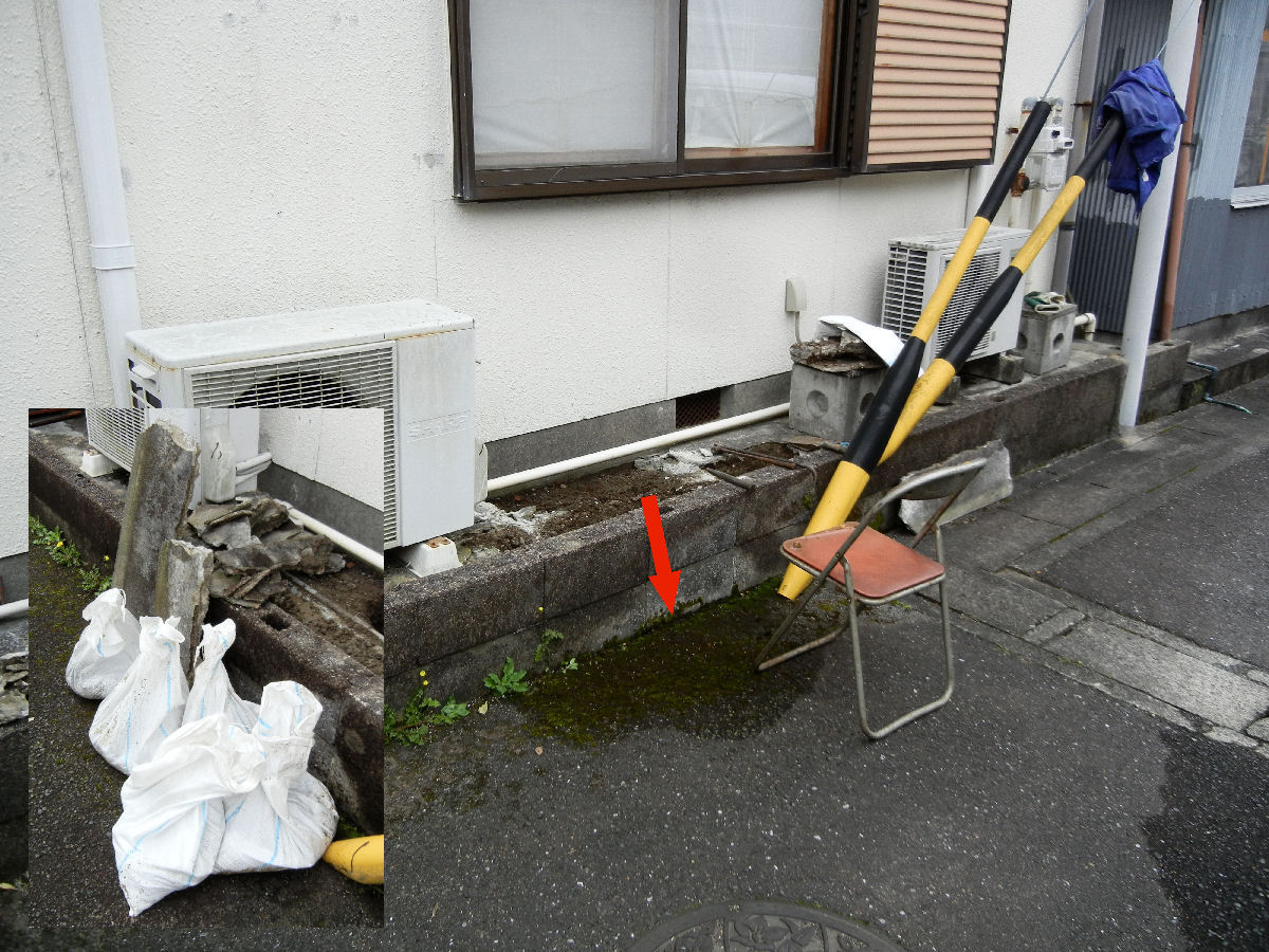
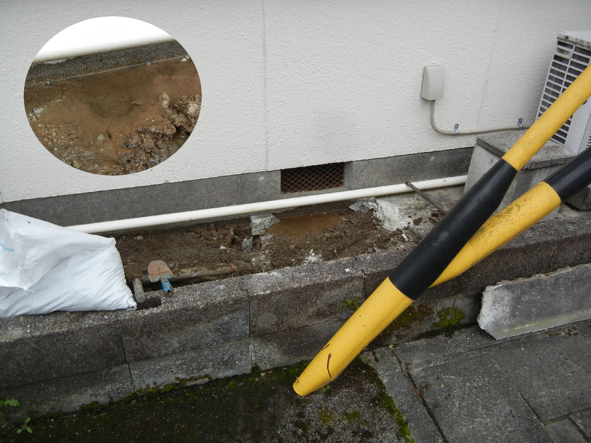
Repair Of The Water Leak 2
(Installed on 2024/04/23)
―1/5―
―2/5―
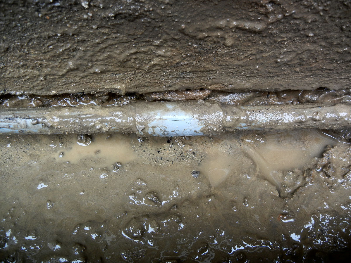
―3/5―
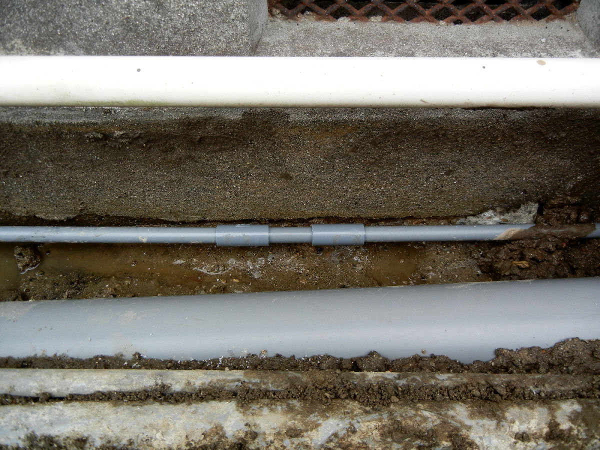
―4/5―
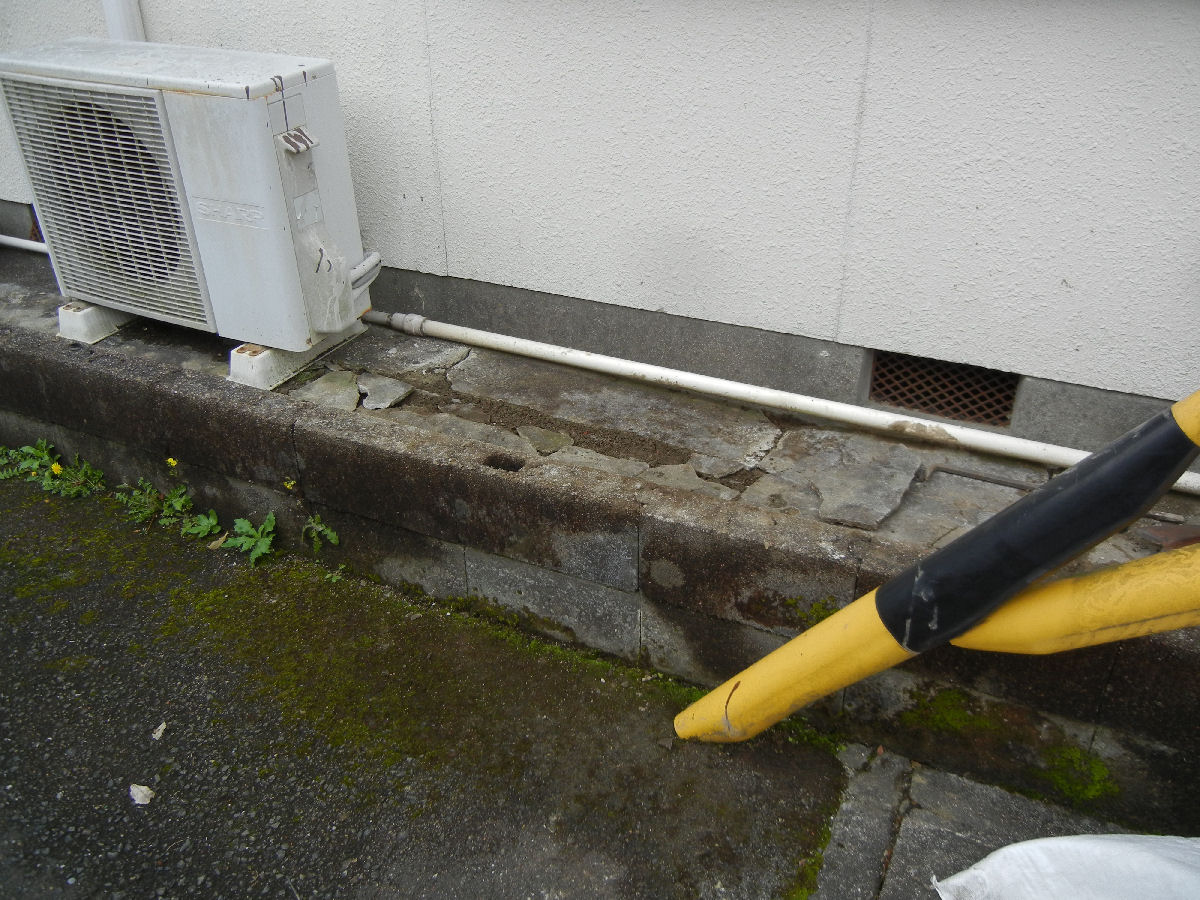
―5/5―
Return to the list.
Mending The Broken Ceiling
(Installed on 2025/10/10)
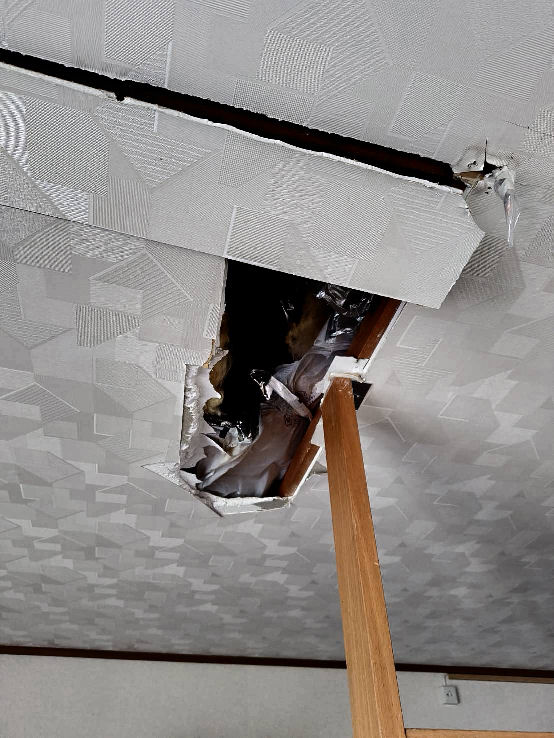
―1/5―
―2/5―
―3/5―
―4/5―
―5/5―
Returen to the list