Playing House Kitchen Counter

kichen counter m.jpg

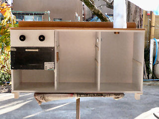
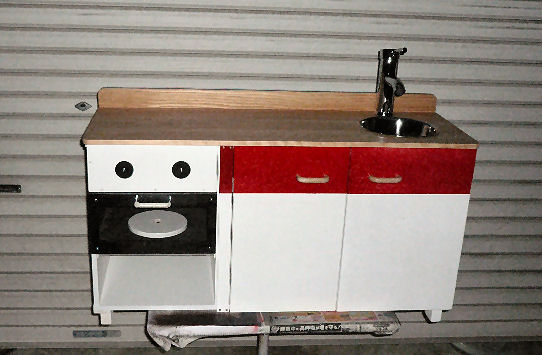
Play house kitchen counter built on a box sold on the market
One day in late November in 2015 my daughter asked me if I could make a play house kitchen counter utilizing a ready-made colored particle board box for her daughter. I was ignorant of a play house kitchen counter. She showed me various types of such counters. It looked interesting to try and I did it. I could deliver the counter as shown in the photo on Christmas Eve.

-1/27-

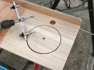
sink hole1.jpg

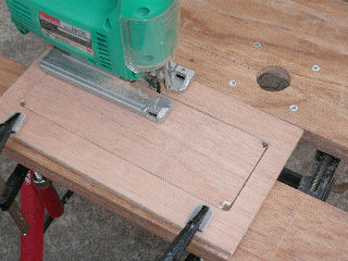
Cutting holes for a faucet and a sink on the top plate.
A 200mm caliber stainless bowl is planned to use as a sink.
The material of the top plate is glued laminated timber and that of the end plate is prywood.
The plate is about 10mm wider and 20mm deeper than the colored box so that the top plate makes eaves in front and on both sides.

-2/27-
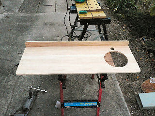
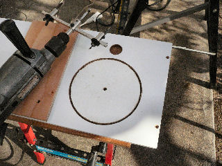
sink hole2.jpg

The top plate ready to be painted.
In cutting a hole, it is an iron rule to do it from both sides. I had forgotten it and when cutting the bigger hole, I did from upper side only and made the cut end on the other side ugly.

-3/27-

sink hole3.jpg

cutting the same holes on the colored box.
Cutting holes on a particle board is more difficult.

-4/27-

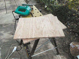
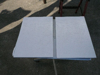
door1.jpg

Cutting doors from a 900mm*1800mm*12mm plywood.
I was afraid if they were a bit too heavier but actually, they weren't. Besides, 12mm thickness was good for fitting hinges with screws.
Those plates needs sandpapered on all the edges in order to protect them from damage.

-5/27-
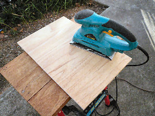
door polish.jpg

Sandpapering on surfaces with care not to damage edges.

-6/27-
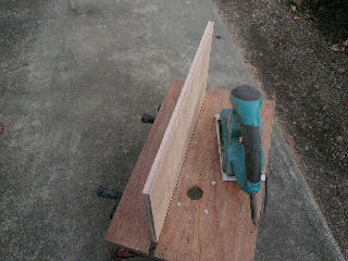
door polish2.jpg

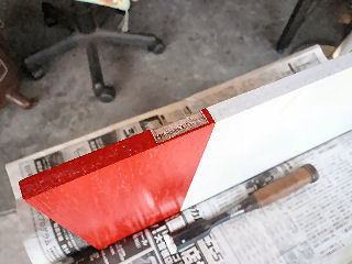
Sandpapering on cut ends.
The corners had to be made round and smooth for safety's sake, which I forgot. I did it after finishing assembling.

-7/27-

door painted white.jpg

Painting doors white.
They were partially painted red after this with masking unnecessary portions. I forgot to take a photo of that process.

-8/27-

hinge hole1.jpg

Carving a hinge pit.
It should have been done before painting!!
I was too fool to take the right door from the left, which I found only after finishing carving.
I used 25mm-long screws for fitting hinges for sturdiness.

-9/27-
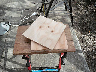
shelf board.jpg

Shelf boards ready to be sandpapered and painted.

-10/27-
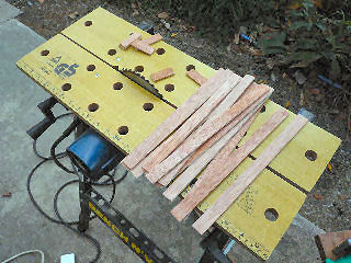
shelf catch.jpg

Making shelf rests.
Their polishing and painting can be done simply as they are used inside the counter not to be seen.

-11/27-

range window1.jpg

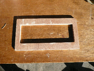
Making an oven lid.
It will be made windw-like with 1.5mm-thick acrylic board.
I grued 5mm and 3mm boards, for 12mm board seemed too thick. So, the lid became 9.5mm thick in the end.

-12/27-
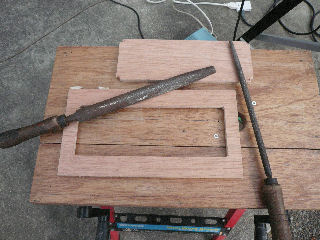
range window2.jpg

Finishing the window frame.

-13/27-

range window mending.jpg

Applying putty to broken edges.
The 3mm board was too old to be cut without damaging edges.

-14/27-

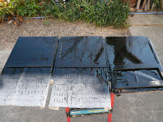
painting black.jpg

Painting the portions of boards that face the inside of the oven.

-15/27-
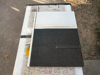
partition ready.jpg

Painting finished and shelf rests fixed.

-13/27-
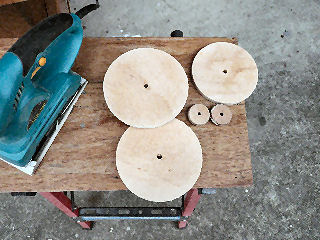
plates and nobs.jpg

Making an oven roter, range trivets and adjuster nobs.
I used remainder wood of speaker making.

-17/27-

half assembled.jpg

The counter half made.
The top plate, heat adjusting nobs(they can be turned by hand), the faucet and the oven assembled. The faucet is covered with plastic sheet to keep it from being scratched.

-18/27-

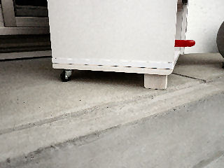
leggs.jpg

The hind legs are casters for movability
While the front legs are wood to make it settled at the spot. Legs are fixed on plates as assembly.
The leg plates are necessary for metal fittings to be attached on which are fixed braces as shown below.

-19/27-
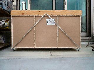
back view.jpg

Ready-made color boxes are rickety to side ways.
With braces installed as shown in the photo the box becomes firm.
The bottom ends of the braces are fixed to the ends of particle board with metal fittings. Without them particle board is too weak for resisting the stress on the braces.

-20/27-
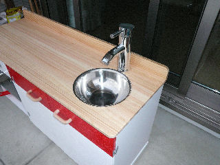
sink close-up.jpg

An upper sidelong view of the counter.
The faucet seems a bit too big but fortunately, the granddaughter didn't care at all.

-21/27-

under sink inside.jpg

A veiw of the inside under the sink.
There are three shelves behind the other door.

-22/27-

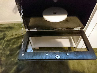
oven inside.jpg

A view of the inside of the oven.
The rotor is manually rotatable.
To the lid is installed a chain to stop it from being opened too far. Otherwise, the hinges will be broken.
As an injury proof, the four corners of the lid are made round. I did the work after I delivered the counter. It should have been done before painting while making it.

-23/27-
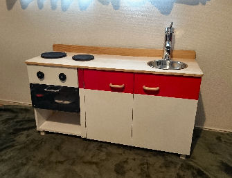
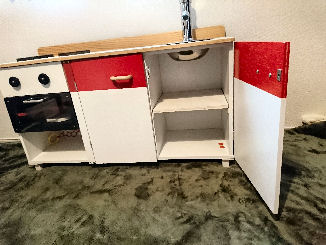
delivered.jpg

The counter after it was delivered
to our granddaughter's house.

-27の24-

Postscript
I barely managed to deliver it on Christmas Eve. To meet the deadline, I had to work later in two evenings in a hurry and it begot some failures.
1. I forgot to load shelf boards in the car when I loaded the counter on board.
2. I didn't work on the corners of the lid and doors to make them round before delivering.
3. I had to change the design of the left door and its fixing. Original design turned out that the door and the oven lid interfere each other. I had to add a sub fixing plate.
4. As I hurried the painting of the sub fixing plate, I couldn't paint it beautifully. The red portion should have been painted after the whole plate was painted white as I did it with the doors.
5. I forgot taking photos of some processes.

-25/27-

Chief parts list
colored box W:420 D:29 H88.5 YamazenThree Shelves White GCB-3 ¥2000(carriage included) faucet A-Omega copper pyrites electro plated combination faucet X000CTC51L ¥2160(carriage included) stainless bowl 200mm¥480 glued laminated timber ¥1380
prywood 900*1800*12 color spray white@ ¥848*3 color spray red ¥748 color spray black ¥748 rubber caster 25mm ¥88×2
magnet catch ¥238×1, ¥98×2 hinge ¥128×3 door handle chrome¥190、wooden ¥180×2 acrylic board transparent SS 1.5mm  ¥448

-26/27-
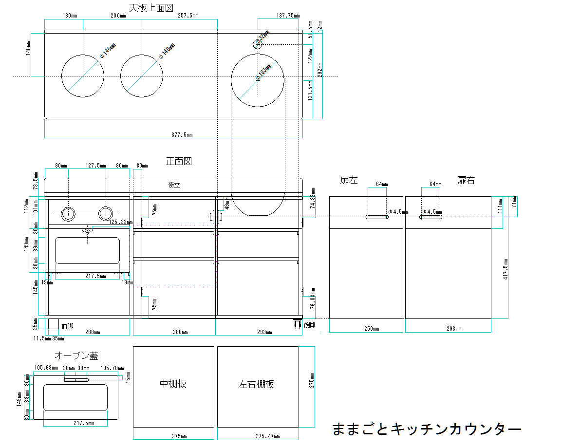
Plan in Japanese

play house kitchen.jpg


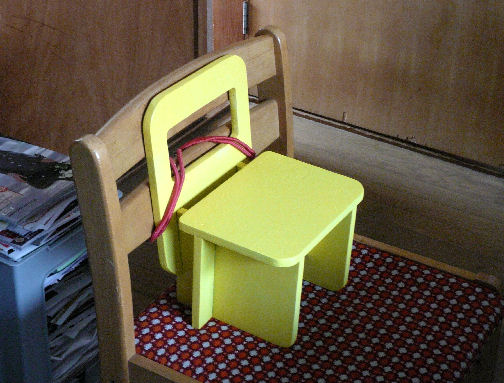
Granddaughter's Chair

grandchild chair m.jpg

Our granddaughter who was two and a half years old started to visit us during her mother's maternity leave and she needed a chair to use on a usual chair at the tale.
I asked her what color do you like it painted? She immediately answered "yellow!" That's why it's yellow.
To my regret, the chair was not stable enough for a little child to use. There are always something new to learn for an old D.I.Y. carpenter.

-1/1-
Return to the list


Paper Rack For Printer

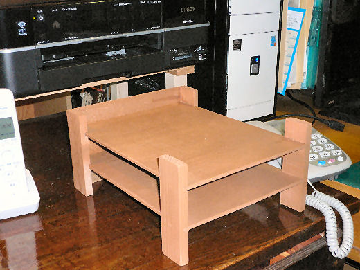
pc paper rack m.jpg

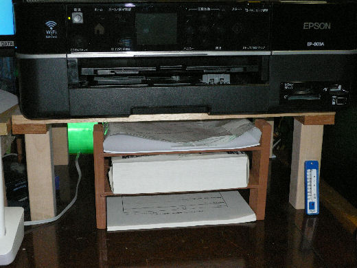
To put and keep printer paper in order had been difficult. I had been keeping them on a book shelf but it wasn't a good place.
I raised my printer as shown in the photo and placed a paper rack underneath.
I made the rack with the remainder wood. To secure more vertical space, it has neither top nor bottom plate.

-1/3-

.jpg

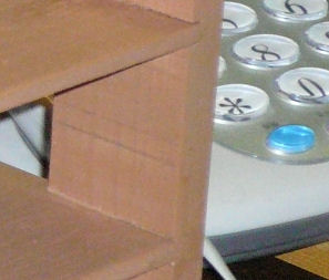
For taking paper in and out smoothly, I morticed shelves into pillars and glued them, which made the rack handy and strong enouh.

-2/3-

.jpg

I have been using them as shown in the photo, sorting A4 at the bottom, B4 in the middle and others on top.
A rack like this must be one of the best ways of keeping printer paper ready to use.

-3/3-

Return to the list


Document Sorter

sorter.jpg

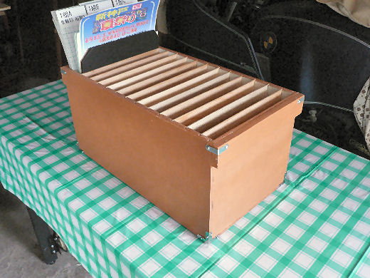
When I was taking charge of responsibility for the neighborhood association, every month I had to sort a lot of documents which were commissioned from the municipality.
At first, I was sorting them on the floor but the job was very irritating and time consuming. So, I made the sorting box as shown in the photo.
The box is designed to weigh light so that it can be easily carried by using falcataria board.

-1/1-

Return to the list


Retractable Table

folding shelf off.jpg

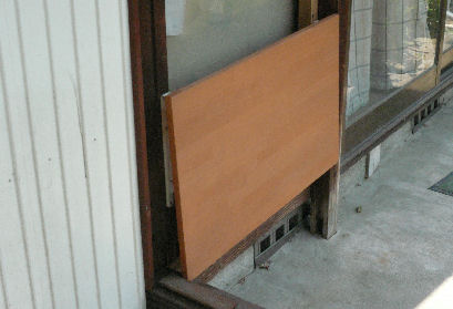
I installed this rack(table?) in order to place things temporarily. You often need a clean place such as this when you come back home, for example, from shopping.
The shelf can be folded as it is shown in the photo below. I'm trying to fold it down when it's not used.

-1/2-

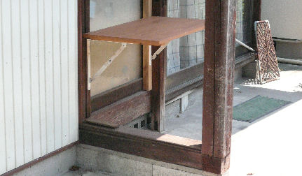
folding shelf on.jpg

Why is it needed to be folded? It is because otherwise the shelf becomes eternally occupied with things left there.
However, the idea was too optimistic. Things started to be left in front of the rack and it became impossible to lift it up!

-2/2-

Return to the list


Wooden Board Holder

fixer.jpg

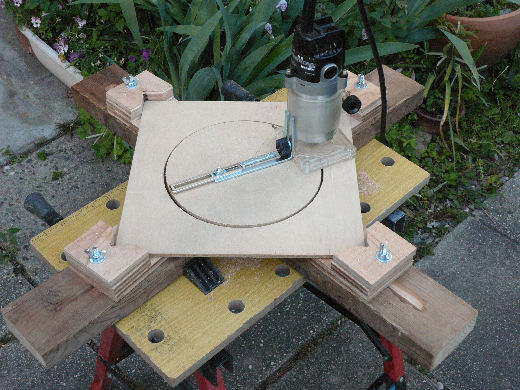
The photo shows the holder on which a piece of board is held tight and a circular piece is cut out of it (or a hole is cut on the board).
The holder can be adjusted to the various size of stuff. It is one of the most frequently used tools in my workshop.

-1/1-

Return to the list


Wind Shield

wind shield installed.jpg

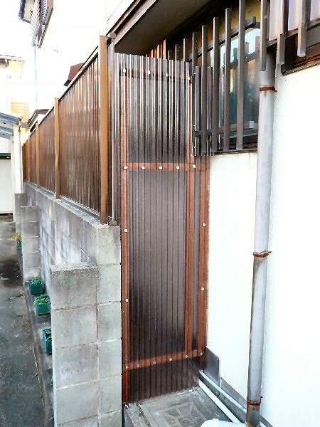
I installed a shield in order to block freezing winds.
Cold north-west winds, though only a few times in one winter, freeze the tap water installed between the next door wall and our house.

―1/6―

back space before.jpg

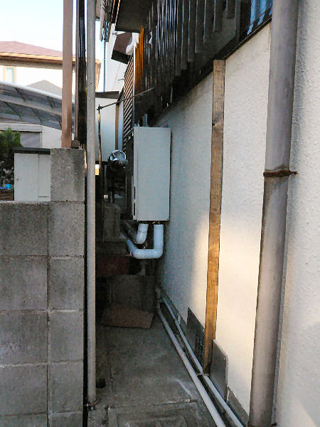
The space was open before as shown in the photo.
It was forming a kind of an air tunnel where freezing winds run through.

―2/6―

wind shield frame.jpg

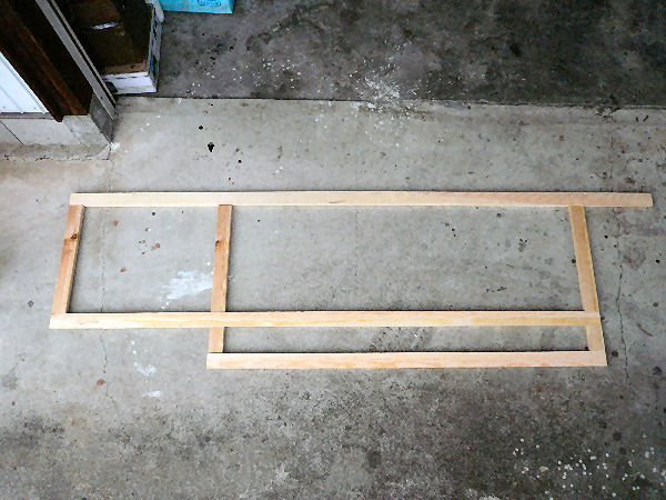
A wooden frame on which a piece of corrugated polycarbonate sheet is to be fixed. It was finished after a preservative treatment was given.
The completed frame was a little too small in width than it should have been. I'm always poor in sizing.

―3/6―

stay and prop bases.jpg

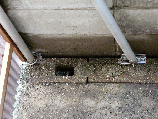
The photo shows the bases of the prop and the stay. The pipes were cut out from the old HF antenna boom.
They are fixed to the concrete blocks with pieces of stainless steel L-shaped beam.

―4/6―

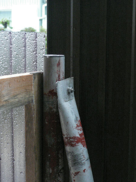
prop top.jpg

The prop and the stay are fixed as shown in the photo.

―5/6―

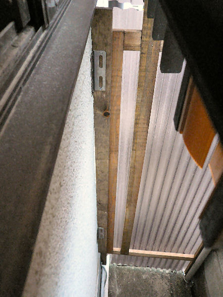
inside wall mount.jpg

The wind shield is fixed to the concrete wall with pieces of L-shaped stainless steel beam.

Thank you for reading to the last line.

―6/6―

Return to the list


Pc Rack On The Wall

(Installed on 2021/02/03)

1-wall pc ready.jpg
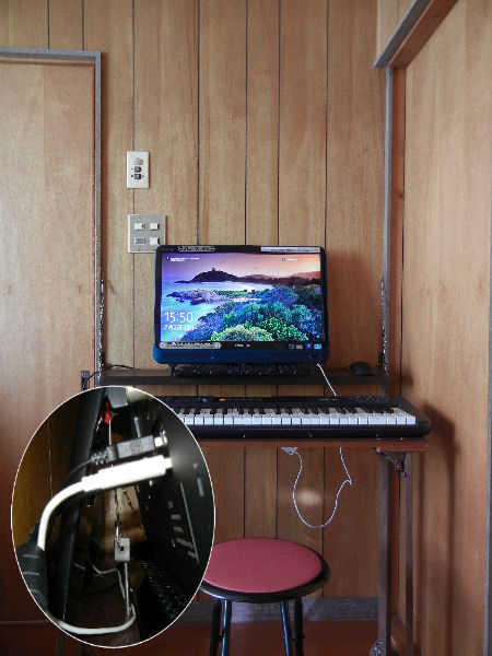
The REGZA PC which luckily became a member of my pc group the other day is a window pc all built in the monitor body. That is, it's space economizing. So I made a shallow rack on the wall to place it. I hesitated to impair the wall but I finally screwed metal fittings at four places in order to hold the rack, for which I used some remaining wood boards.

1/6

2-putting boards together.jpg
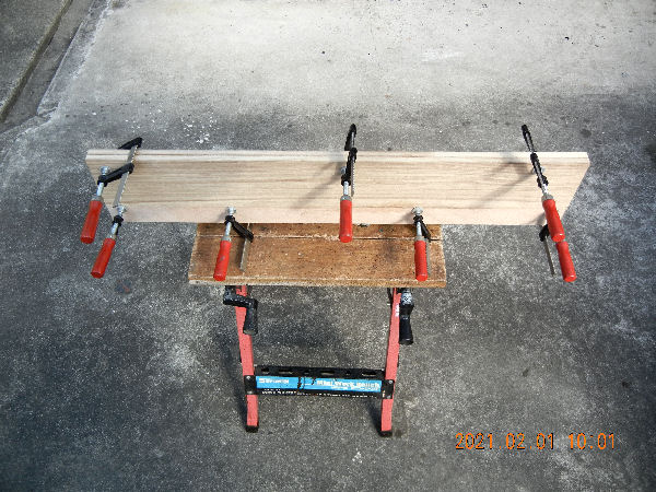
I had some suitable sized boards for the rack but they were thin. So, I glued two thin boards into one stronger board.

―2/6―

3-drying paint.jpg
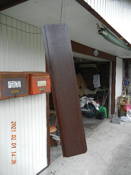
The direction on the spray can said it should be used when the temperature is higher than 7 °C. I painted the board around noon as max temp on the day was 10 °C.

―3/6―

4-metal fittings.jpg
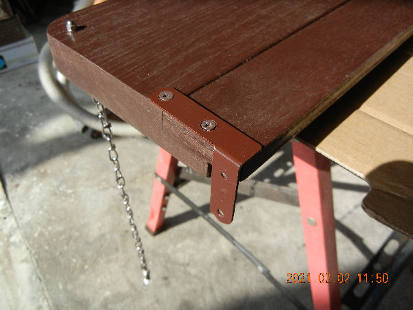
The photo shows the metal fittings with which for the rack to be held onto the wall. The rack can be folded up when necessary.

―4/6―

5-rack attached wall.jpg
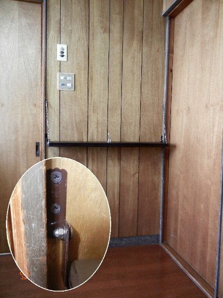
The rack was installed onto the wall as in the photo. The oval window within the photo shows a hinge.

―5/6―

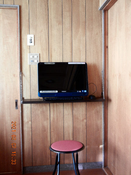
6-wall pc and keyboard.jpg

The photo shows the pc being used on the rack. The pc is anchored with a piece of stainless wire and a bolt as shown in the oval window. It is pulled downward by turning a wing nut on the underside of the rack.
It turned out that a pc in the living room is handy for internet surfing. Incidentally the keyboard is for our grand daughters but it is also a source of MIDI signals now.

6/6
Return to the list.


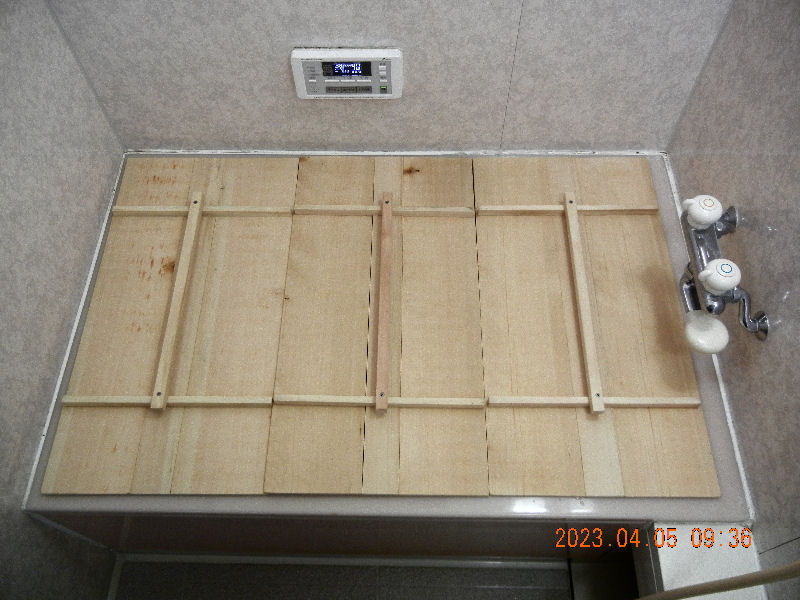
0_finished_s.jpg

Bath Tub Lid


(Installed on 2023/04/06)

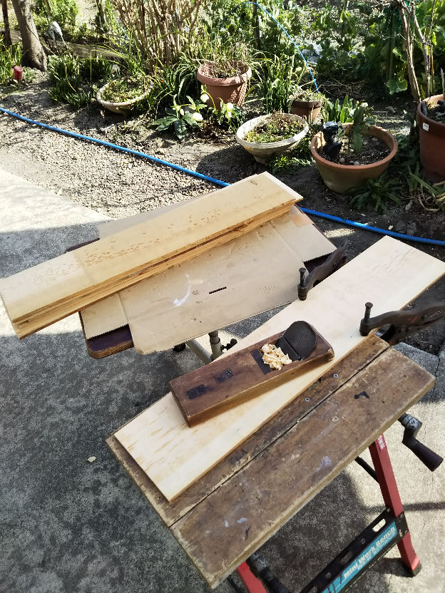
1_planing.jpg
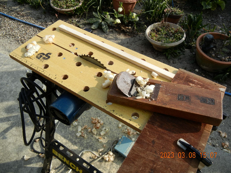
The old lids which my father had made and left to us for the old bath tub are still usable but they are a little too small. I had planned to make new ones and bought some pine boards many years ago only to keep. When I repaired the solar water system the other day I recalled the old idea. I checked them and found they were as new as I bought them back home.
I set about planing them but alas I no more had enough physical strength to plane all the boards.

―1/5―

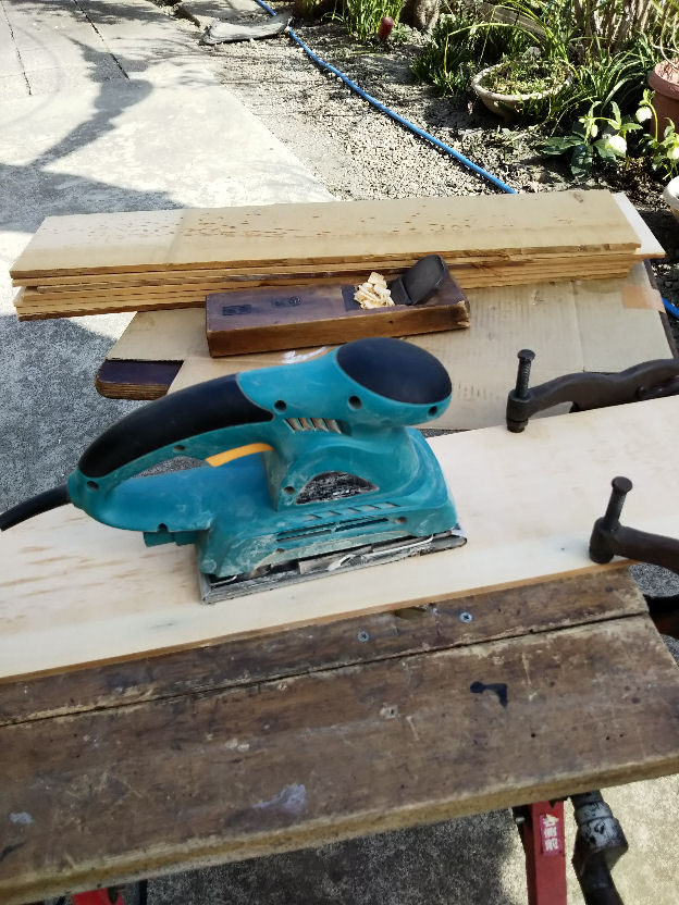
2_disc sanding.jpg
I exchanged the plane for the disc sander. It makes big noise but it was a little chilly day and the widows of the houses around were all shut. I dared to do it.

―2/5―

3_making cross piece.jpg
I made cross bars from a big and longer rectangular lumber too.

―3/5―

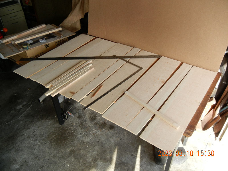
4_ready to be put together.jpg
The photo shows all the boards and cross bars for a set of three lids. I was afraid the boards were a little too thin. I would buy thicker boards next if my life allows it?

―4/5―

5_finished.jpg
The boards were finished as shown in the photo. I applied harmless waterproofing spray all over them wanting for them to endure longer .
The solar water heating system makes 80℃ hot water soon after noon during warmer seasons. We fill the tub about 1/3 then covering it with the lids. The hot water is still hot enough in the evening.
We used them the other day for the first time. The bath room was being filled with the aroma of pine.

―5/5―

Return to the list


Tower For Amateur Radio -1-

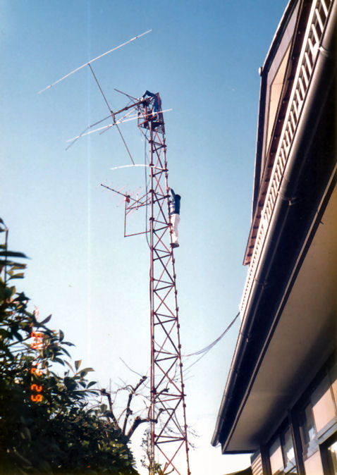
antenna painted.jpg

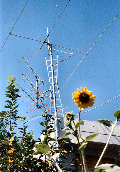
When younger, I was a radio amateur (I am still but only by name).
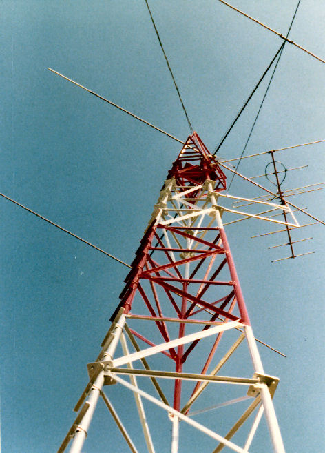
I installed an antenna on top of the 15-meter high tower to have shortwave communication with amateur radio stations overseas.
It took several months to construct the tower as shown in the photo 1. Thanks to the construction work, I became skillful in welding.
For the base concrete, I ordered sand and pebbles of five 4-ton trucks and mixed them with Father and my brother. I buried 1m block of the tower into the base concrete.
The tower above ground consisted of three blocks. From the bottom, two 5-meter blocks, one 3-meter block and one 2-meter block with a working cage on the top.
The upper blocks were pulled up by a car using two pulleys, one at the bottom and the other at the top of a stout long log.
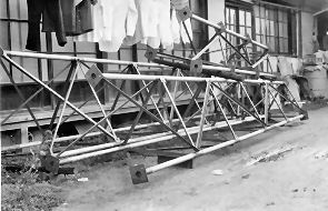
Photo:Two 5-meter blocks and one 3-meter block that were assembled. The building behind them was my old house.

-1/5-

welding done.jpg

Later, when I opened a 2nd class station, I replaced the hand made antenna which is shown in the photo 1 with TA33Jr to work on 14MHz band. The photo 2 shows it being lifted up.
The old antenna was a mono band yagi for 21MHz band. The boom was a gas pipe and the elements were aluminum pipes. It got married to JA2NOI.

-2/5-

lifting antenna.jpg

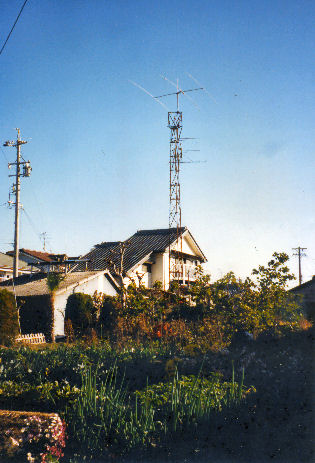
The photo is a distant view of the tower and the antenna in front of our house.
Before constructing the tower, I looked for towers in my area and watched them to learn how they were made.
I calculated the length of parts with a mechanical calculator.

-3/5-

tower.jpg

After completion, I painted it once every year. Painting later became harder for me every year. Besides, the tower was a cause of worry each time a typhoon came. Luckily, the tower survived for about 24 years without being damaged by a typhoon until it was removed.

-4/5-

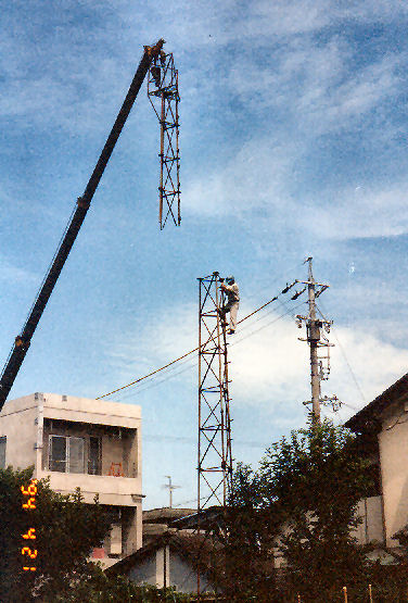
19940421tower removal1s.jpg

On April 21st in 1994, I had the tower removed. I watched the work with the feeling of desolation and appreciation.

-5/5-

Return to the list


Tower For Amateur Radio -2-

.jpg

As I got older, the maintenace of the tower and the antenna became a big problem. So, as my brother next door built a three-story house, I asked him for me to move my antenna to his housetop so that I can remove the tower.
He accepted my request and I moved the antenna for ham qso as well as those for TV. We shared the antennas for TV.
After moving, the antenna for ham qso was once damaged by a big typhoon, which never happened while it was on the old tower.

-1/2-

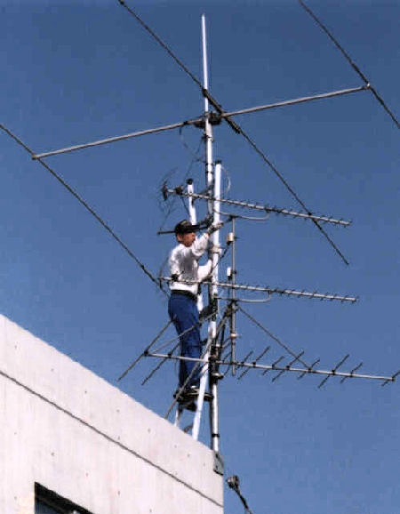
nt under construction.jpg

The photo shows how I worked on the antennas on the new pole. The work became much easier and safer than it was before.
Later, my brother wanted to set up solar cells and I ended my ham QSO and removed the anttennas.
I have been still in touch with the Australian ham with whom I had had regular communications every Sunday for longer than 20 years by way of telephone and email.

-2/2-

Return to the list


Big Compases

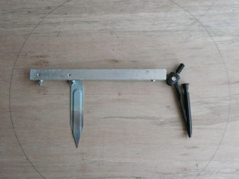
fin version expanded compasses.jpg

For my next project, I needed to draw big circles that are 40cm in diameter. So I made a compass expander.
Materials are
1. A pair of compasses.
2. A piece of u-shaped aluminum angle (to be used as an expanded compass).
3. A blind lid of a desktop pc expansion slot (to be used as a pivot after sharpening one end and then its point quenched).
4. A plastic piece (to be used for fixing a compass).
5. A few screws and nuts.

-1/3-

expanded compasses1.jpg

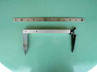
I first used a piece of stainless steel with holes as an expanding arm but it sagged and the circles drawn were not true circles.

A piece of u-shaped aluminum angle solved the problem.
However, it turned out that the length of the arm had to be adjusted for drawing more various sizes of circles.
Thus the expander was finalized as shown in the first photo with two fixing screws for the pivot.
The pivot can be a little more shorter.

-2/3-

top view expanded compasses.jpg

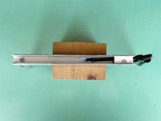
The photo is a top view of the expander before revision.
The expander doesn't have two pivot fixing screws yet.
The original compasses can be taken off by loosening the screw on the plastic piece.
It doesn't have a knob or a handle but you can draw a circle easily.

-3/3-

Return to the list


Hoist In My Workshop

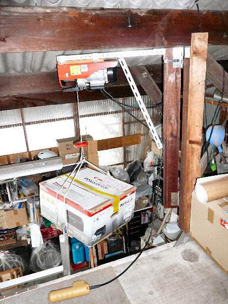
hoist.jpg

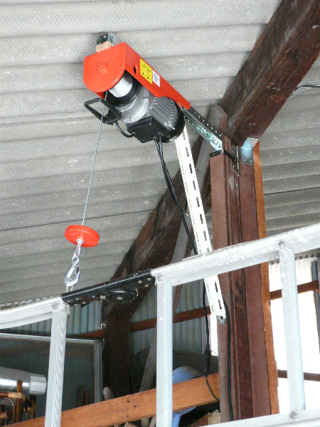
My workshop has an attic. It had been a tough work to lift up or down things before.
It can sway horizontally with two big hinges.
When it's not used, it hangs a ladder on the hook ready to be used as shown in the photo.

-1/2-

hoisting m.jpg

I bought it in 2012 when I started my workshop. The price was very reasonable. I worried about the quality but so far it's been functioning OK.

-2/2-

Return to the list


Installing A Screen Door

(Uploaded on 2019/06/07)


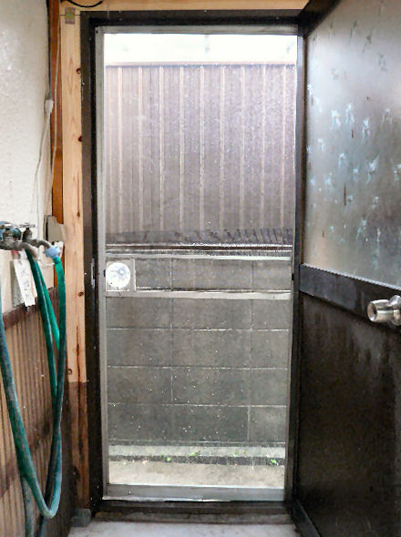
I installed a screen door to the storage door.

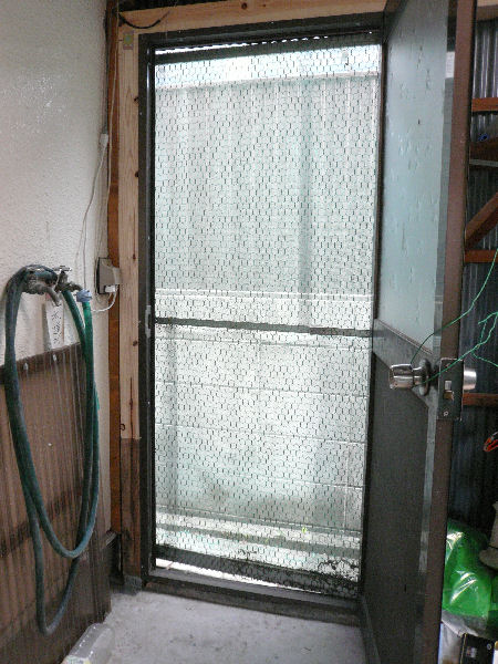
screen door after.jpg

With its tin roof the storage gets very hot during the summer. For ventilation you can keep the door open but it allows all the bugs and mosquitos to come in. So I reformed an old screen door and installed it as you see in the photo. My wife had badly wanted one.

―1/6―

screen door before.jpg

The photo shows the screen door before it was reformed. It was wider than the door frame but used chiefly to keep out homeless cats as well as to keep in our cats we had kept in the storage.

―2/6―

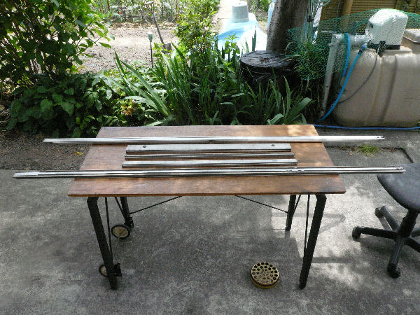
washed and dismantled.jpg

The photo shows the frame and a beam(piece) washed and dismantled (and again washed).

―3/6―

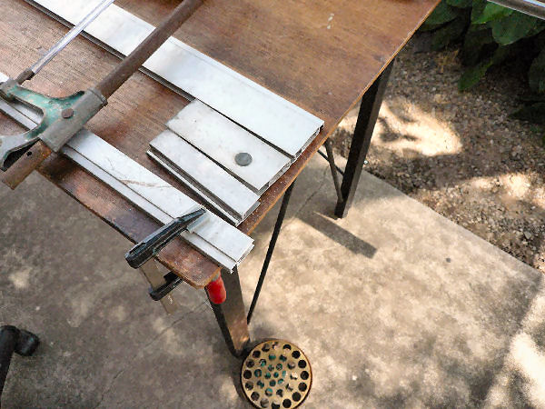
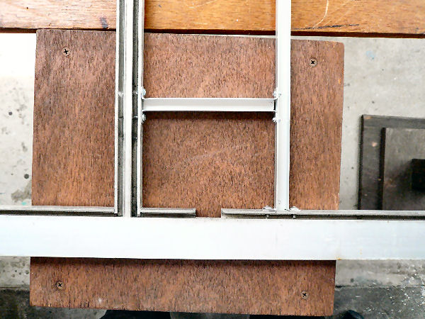
cutting beams.jpg

In order to reduce the width I cut the beam and the crosspieces. This time I cut 124mm off them with an iron saw (neatly!). At this stage however, I hadn't realized the door nob hit the beam at the center.

―4/6―

installing a nob pocket.jpg

I realized the problem for the first time as I tried to fit the reformed frame to the door. Things are not so easy! I had to solve the problem.
I moved the beam(centerpiece) some two inches downward and installed another beam upword so that I can install a pocket into which the nob can be received. It took two days to complete the measure. DIY is time consuming work!

―5/6―

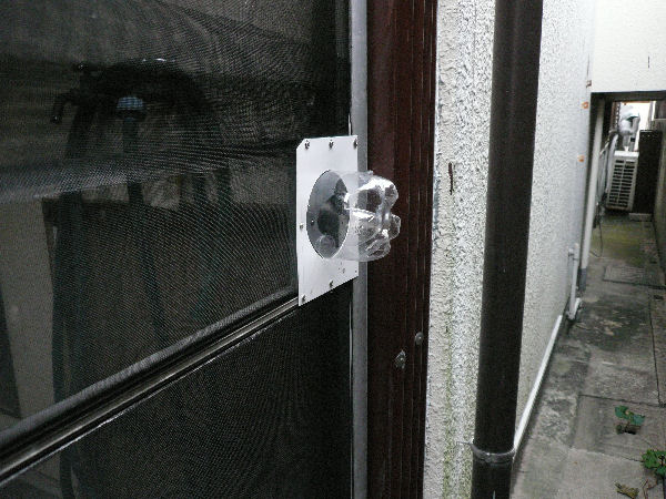
nob pocket outside.jpg

The pocket is installed as shown in the photo. It is made of pet bottle and a piece of vinyl chloride sheet which were put together with synthetic glue.
The space outside is narrow and you can't use hinges to the door that the screen door is set to its place by hands. On account of the new screen door the place looks bery neat now.

―6/6―

Return to the list


Pots And Pans Hook Board


(Installed on 2020/09/27)

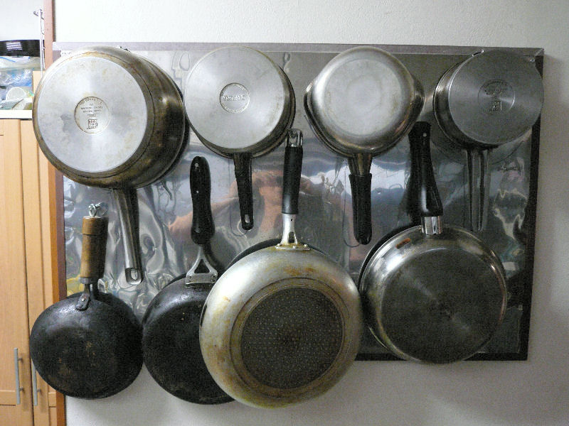
A space saving single action pots and pans board.

1 pots and pans on the board.jpg
I reformed the board left by our deceased son into this hooking board. In his university days he arranged a kind of small bar privately in his apartment house. It seems he had used the board for a cooking counter.

―1/7―

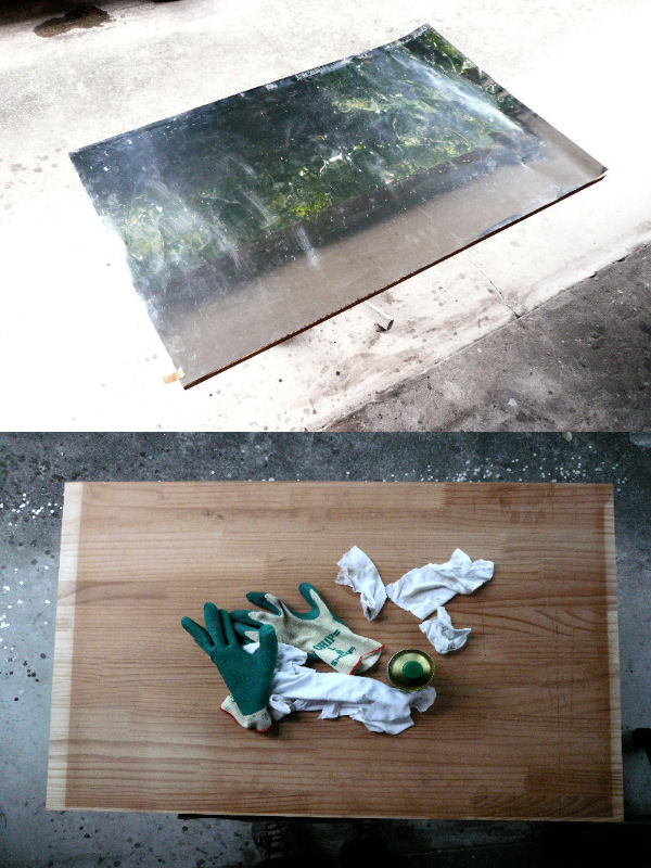
2 original board.jpg
The board was of a piece of laminated wood one surface of which was plated with stainless steel sheet. The sheet was glued on to the wood and the sides were hemmed with black adhesive tape. My first job was to clean the board. The lower half of the photo shows the back side.

―2/7―

3 board fringed.jpg
To finish off the cleaning I installed a new L-shaped plastics hems.  

―3/7―

4 pod hook.jpg
The photo shows a hook. I made the hook to save space. That is, pots can be hooked reversed way of pans so that their slender handles meet in the middle. Bending of stainless steel angles into four equally shaped fittings was impossible. So I canselled the differences by adjusting claw projections for 6mm insertion gaps.

―4/7―

5 hooks installed on board.jpg
The board completed with hooks equiped. With a mirror-like surface the board was difficult to be photographed!

―5/7―

6 how to hook.jpg
The photo shows how you can hook pots. You insert a pot slantwise into the hook and then let it hang vertically. Flanges are diverse and it was impossible to make one versatile hook. So, after a few troublesome process of trial and error I adjusted each hook to have 6mm insertion gap in order to meet all the four pots we hang on the boad.
I faced many troubles while making this hook board but I could finally finished it after three weeks with certification of my wife. Banzai!

―6/7―

A rejected hook .
7 hook first version.jpg

At first I devised a hook as shown in the photo. The mechanism was that being raised upward by a spring while empty it settles down horizontal with a load of a pot with it bottom held not to come off the hook by an upper arm(not equipped in the photo). It looked to be a very reliable device but was not simple enough nor versatile for various pots.

―7/7―
Return to the list.


Toilet Extractor Fan

(Installed on 2020/12/23)

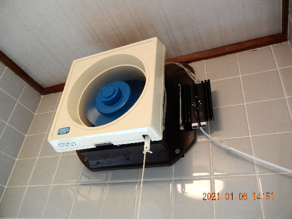
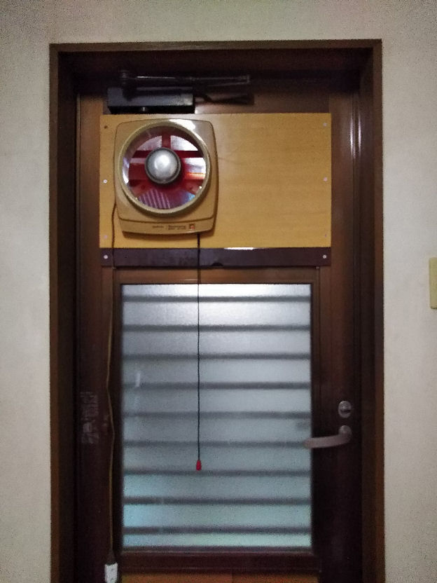
1-extractor fan at work.jpg
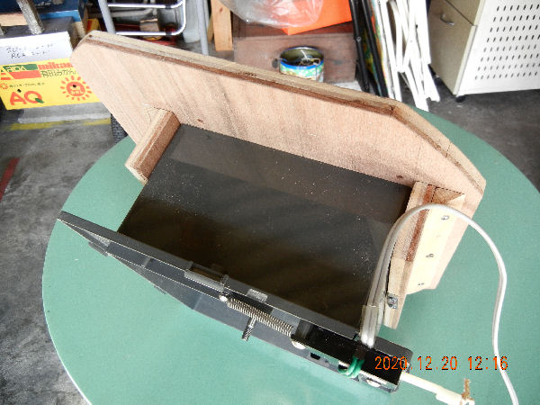
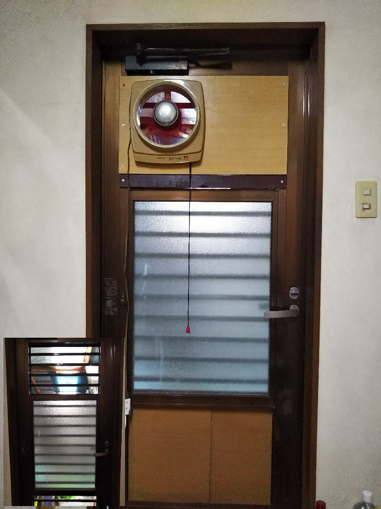
I installed an extractor fan to a toilet. I bought the fan more than thirty years ago but it had been kept aside unused because the size didn't fit to the ventilating opening. I was busy as a young man and lacked tenacity of purpose.

―1/9―

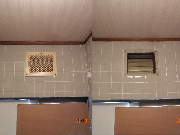
2-original ventilating opening.jpg
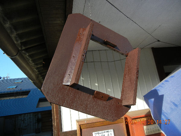
This time I planed to install the fan using a blacket that can be fixed to the wall instead of the louver.

―2/9―

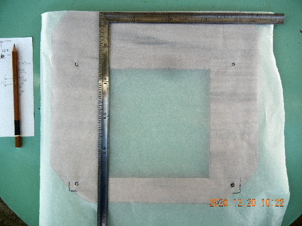
3-screw hole positioning.jpg
I am very poor at sizing and so I made the stencil with a piece of semitransparent paper in order to mark accurate screw hole positons on the blacket.

―3/9―

4-checking the size.jpg
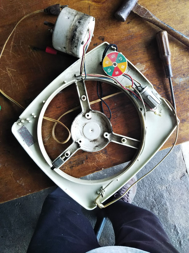
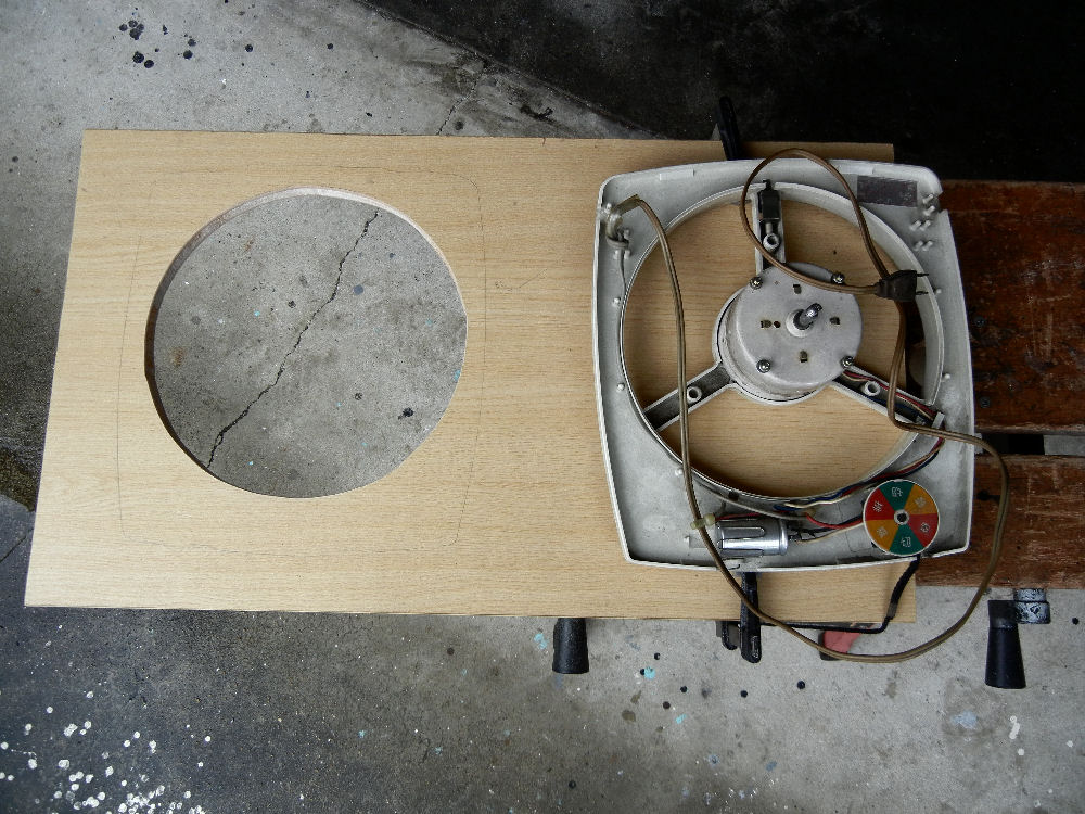
Checking how they fit. The plywood materials are the remains of my past speaker baffle making.

―4/9―

5-drying paint.jpg
Drying the paint.

―5/9―

6-bracket fixed.jpg
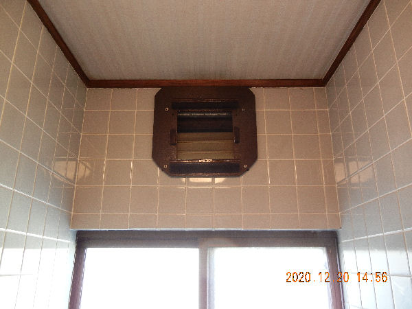
The blacket was firmly fixed to the wall. The base is brittle mortar that I carefully selected the best sized screw to each hole from among several slenderer or thicker ones.

―6/9―

7-extractor fan installedjpg
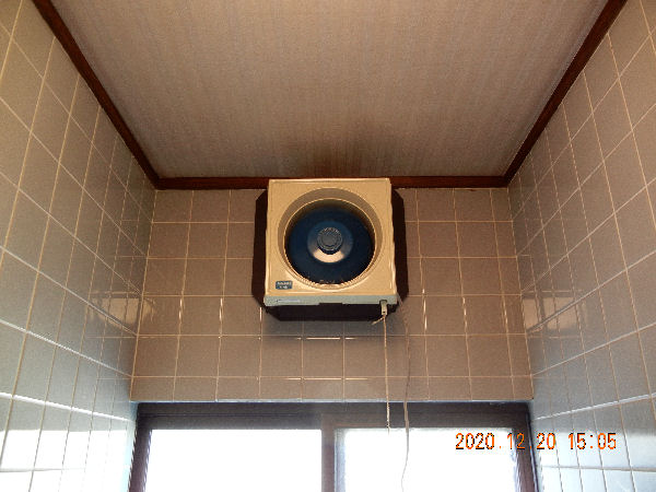
I could tightly fix the fan onto the blacket. However, it turned out that the fan was too strong and so loud was the noise. The revolution must be made slower.

―7/9―

8-voltage dropper.jpg
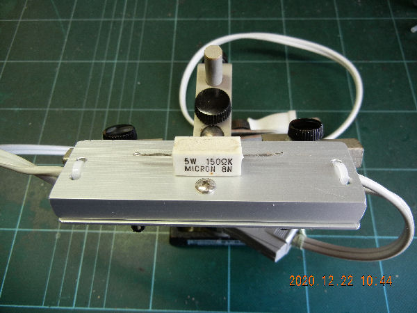
I made a device to drop voltage with a cement registor of 150Ω/5W sandwiched between two pieces of aluminum plate (the resistor on top of the device is only for showing the identical one inside). With the device the voltage fed to the fan dropped from 100v to about 77v, the heat of the resistor being effectively dissipated through the plates. Adjusting power with a triac device is the way smarter but this simple devise serves the purpose enough.
Later, I found a heat sink in my junk box and attached it to the device which is fixed on to the blacket(photo). It would keep it not too hot in summer.

―8/9―

9-2F toilet undercut.jpg

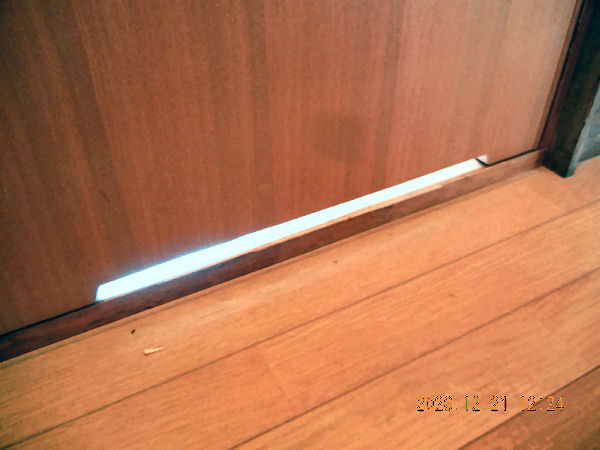
I completed the work by making an undercut air intake onto the door.

―9/9―
Return to the list.


C To D Battery Adapter


(Installed on 2020/02/25)

1-c set as d.jpg
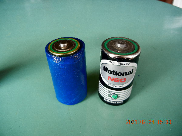
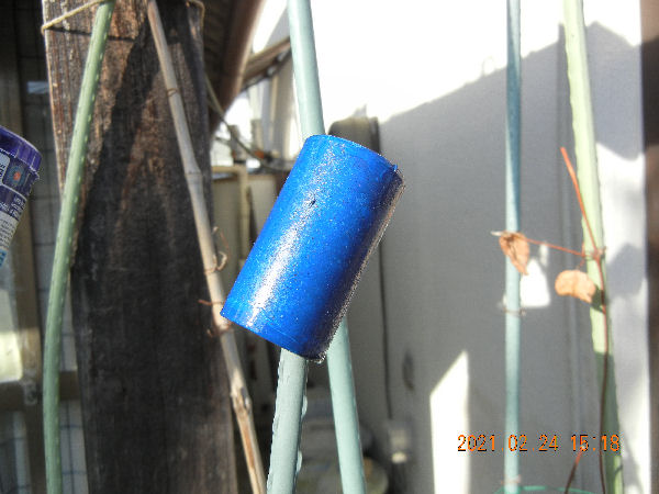
We found we had kept many unused C batteries. They are out of date and not sold. Besides, we don't have any gadgets that use C's, while D batteries are used for igniting the gass range in the kitchen. So, I made C to D battery adapters. The blue one in the photo is one of them.

―1/8―

2-inner case.jpg
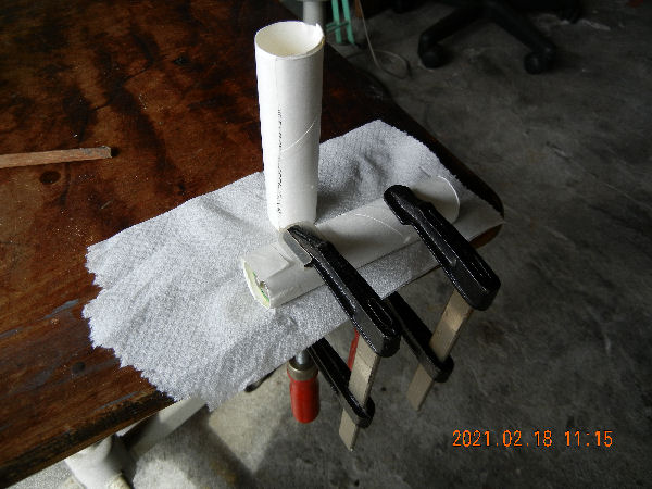
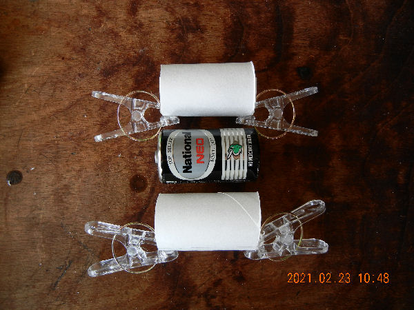
I used tube pieces at the center of toilet paper. The photo shows how I made inner cases, a paper craft with bond.

―2/8―

3-outer cases.jpg
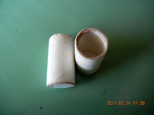
The process of making outer cases.

―3/8―

4-bottom pieces.jpg
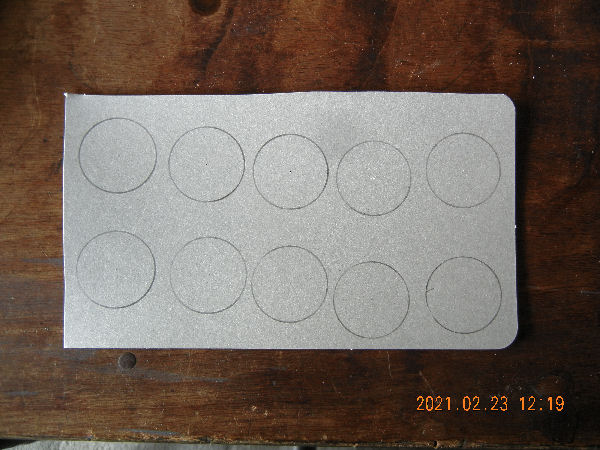
The bottom pieces to be cut. They are piled up at the bottom of the adapters.

―4/8―

5-putty applied.jpg
Three layers of cardboard filled between the outer and the inner tubes. I applied putty for wood to the ends. It made the adapters strong.

―5/8―

6-minus electrode.jpg
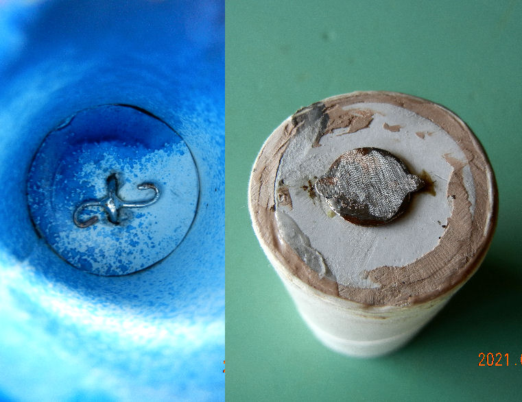
Metal contact point at the bottom.

―6/8―

7-drying paint.jpg
Drying paint. Blue means nothing. I found the old spray can had enough paint.

―7/8―

8-set to use.jpg

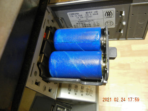
The finished adapters were mounted to the battery holder as shown in the photo. The igniter worked, of course. It seems we have more batteries now than we can spend.

―8/8―
Return to the list.


Mosquito Coil Holder - An improvement


(Installed on 2021/08/01)

.jpg
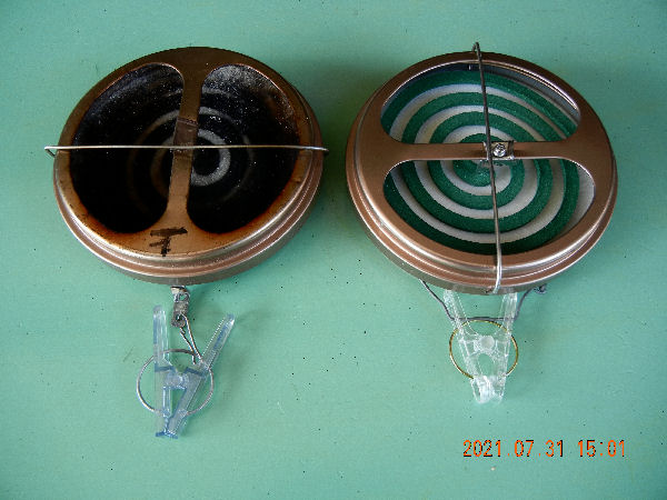
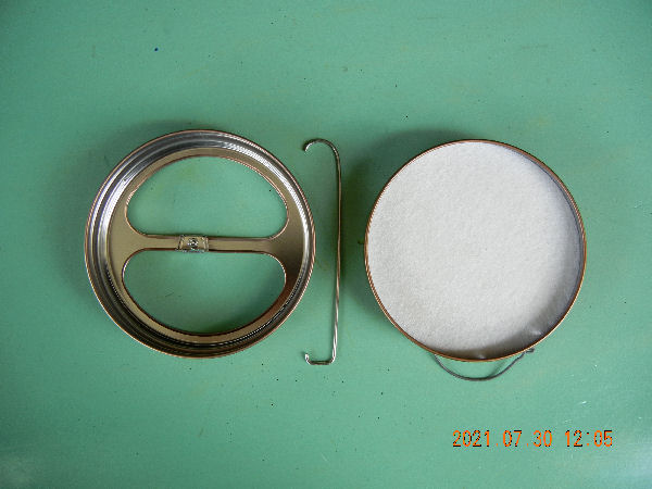
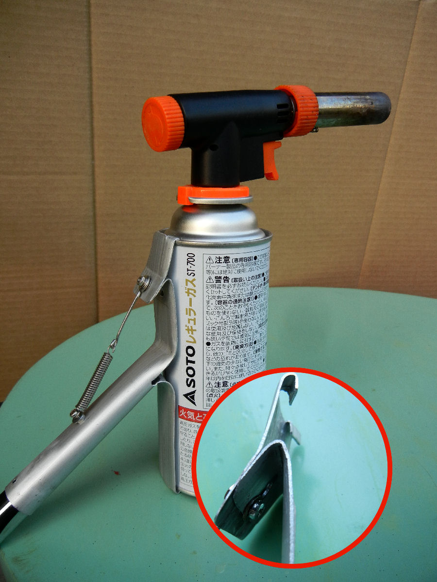
These are mosquito coil holders to be used outside hung around your waist. The one you find on the market uses pieces of glass net between which a coil is held sandwiched. This type is defective. The net gets sooty and the soot finally grows thick enough to extinguish the glow of the coil. My holder, which is open on one side, is free of such defect.
I made a new holder this time applying an improvement on the one I made a few years ago.

―1/5―

.jpg
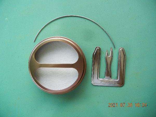
These are materials. You use the holder which comes with coils. The only things you have to prepare are a piece of stainless wire and some screws.

―2/5―

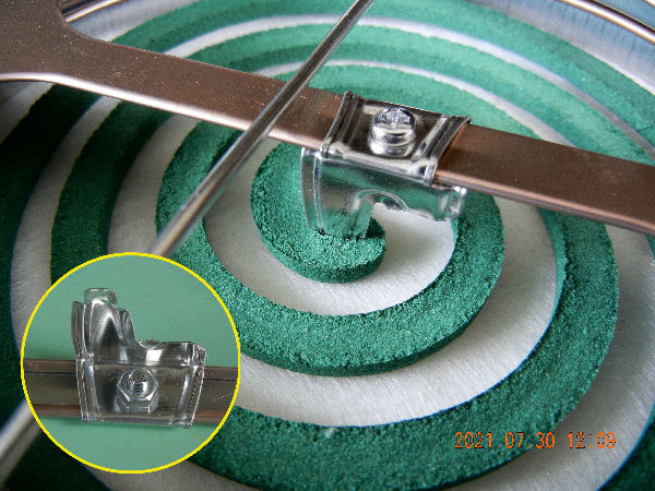
.jpg
The making is simple. You make five needed holes on the holder, the coil stabler to be fit on the cover and the flexible latch for the cover to be locked. Only you have to be careful in making holes as the holder is made of very thin metal.

―3/5―

.jpg
The photo shows how it works. A mosquito coil is held being lightly pressed onto the glass wool. It doesn't come off even whien it slips off to the ground.

―4/5―

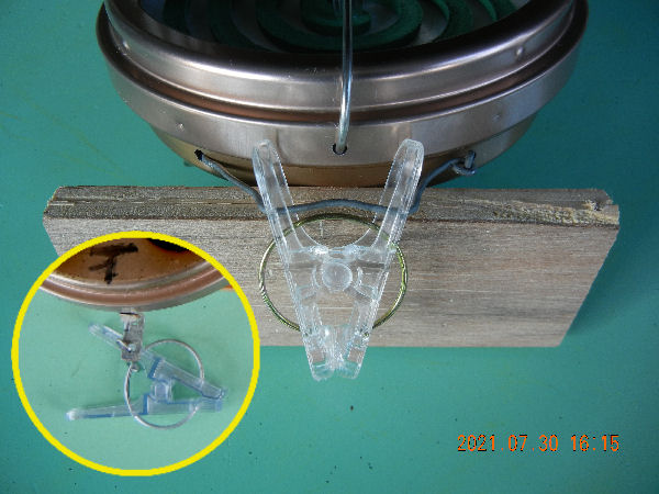
.jpg
I applied an improvement to the hook. The old holder, which is shown in the yellow circle, is hung with a single pivot which allows the holder to easily turn over. The new one is held in two points in order for the holder to face outside always. In addition, I turned around the cover position 90 degrees clockwise intending for the smoke easily goes out.

―5/5―
Retuen to the list.


Jacket Ventilator


(Installed on 2021/08/22)

1-fans equiped jacket.jpg
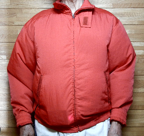
An acquaintance of mine gave me a complete set of jacket ventilator, which I installed to my old jacket for bike riding. The battery is in one of the pockets.

―1/3―

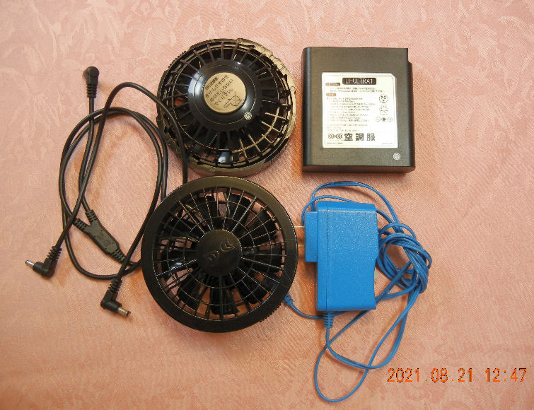
2-jacket ventilator.jpg
The photo shows the set of ventilators. The fan can be installed onto the jaket through the hole catching the cloth between the fan and its fixing ring.

―2/3―

3-bulging jacket.jpg
The ventilator inflates the jaket as shown in the photo. I don't have a big belly. I sewed a piece of rubber band at the waist in order to minimize the air from escaping.
I tried the ventilated jacket. It worked! Cleaning rooms using a vacuum cleaner, which used to be a terriblly sweating labor, smoothly ended without being soaked with sweat. It isn't as cooling as an electric fan placed at your side but it gives you the feeling that you are in the accompanying breeze. The jacket will be a necessity of life during the summer.

―3/3―
Return to the list.


A Larger Grape Trellis


(Installed on 2022/10/03)

1_trellis western whole view.jpg
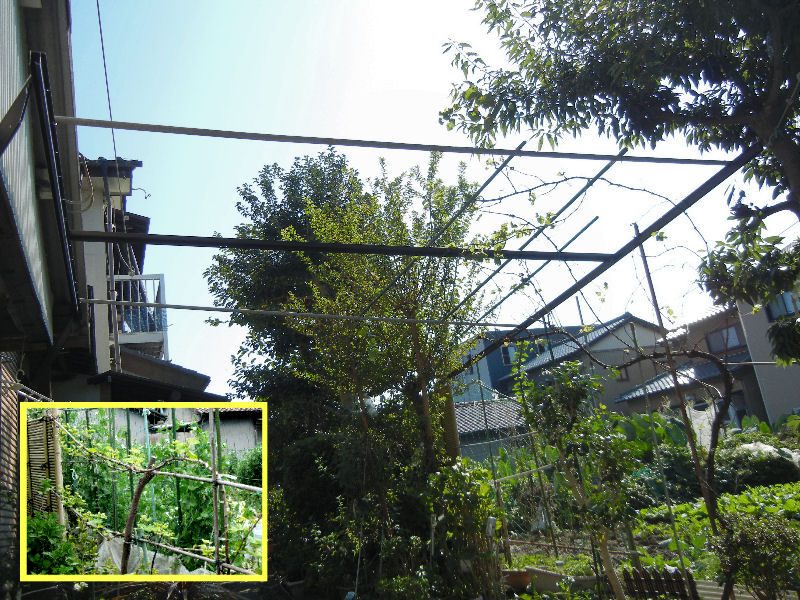
The keepsake grape vine of our late son Tomohiro strongly revived from the scarab disaster after five years. Expecting the more growth next year I built a larger trellis. The photo in the yellow square frame shows the grape on the simplified trellis made along the hedge in 2017, the second year since it was planted.

―1/7―

2_grape trellis material.jpg
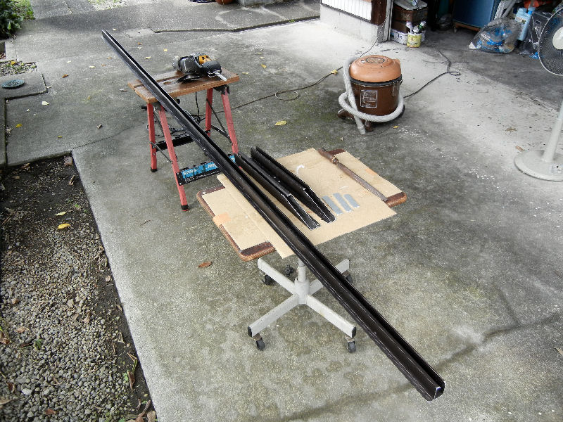
As I had been doing these days I made it chiefly using the leftovers. I bought the cast aluminum extruded beam in the photo many years ago when our roof snow broke the next door carport. I had three of them and I used them all this time, two for the beams and one for the crossbeam. I used two leftover aluminum pipes too for the crossbeams. I have been using up most of the leftovers.

―2/7―

3_grape trellis n_beam.jpg
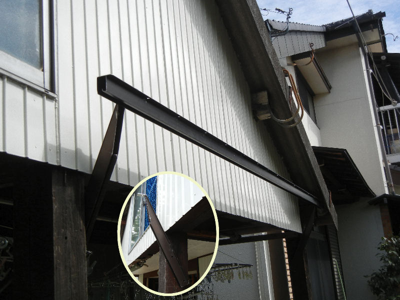
I installed one beam(northern beam) on the pillars of the barn with the brackets I made from the beam. I cut off two short pieces from the beam and made them into the brackets.

―3/7―

4_beam bolted to trunk.jpg
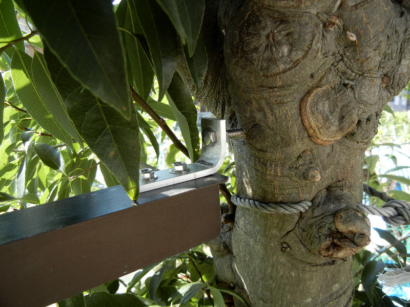
With the other beam(southern beam) I fixed one end of which on to a tree with a stainless bolt screwed into the trunk.

―4/7―

5_sliding beam pillow.jpg
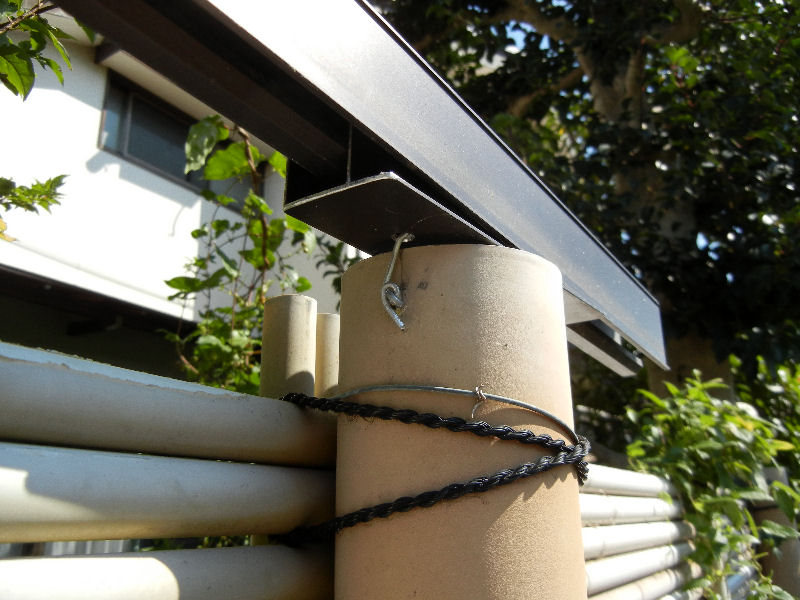
I fixed the other end onto a top of the plastic fence with a pillow. It holds the beam allowing its sliding movement as the tree sways.

―5/7―

6_sliding beam  catch.jpg
The cross beams of aluminum pipe are also slidable on the southern beam providing the sway of the tree. On the northern beam all the cross beams are fixed.

―6/7―

7_trellis eastern whole view.jpg
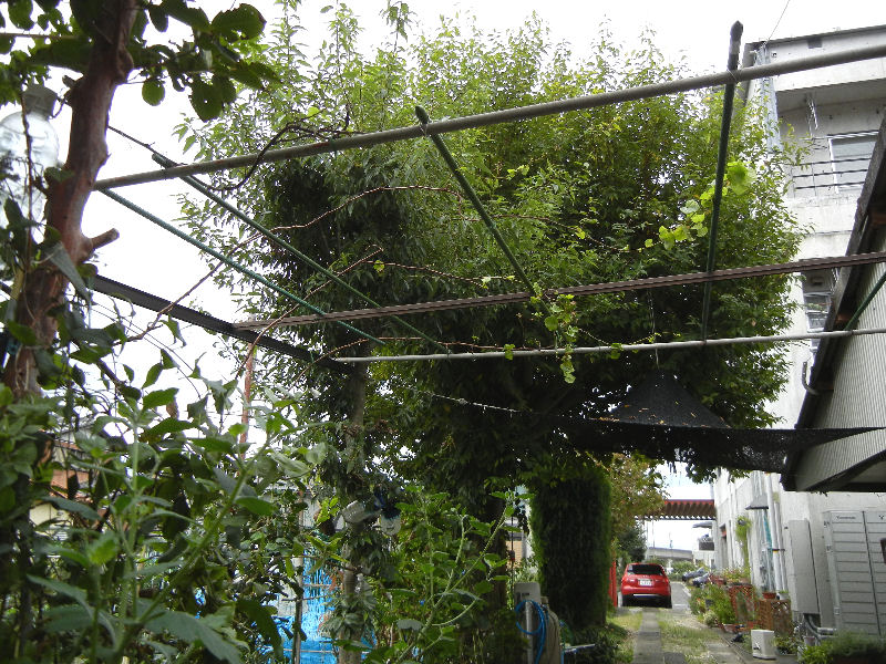
The photo shows the trellis almost completed. It seems more supporting bars are needed for the branch vines. I would have to select promising ones to let them grow on cutting off the lest during the winter. The vine also needs some after harvest manure for the nest year.

―7/7―
Return to the list


0_sofa table.jpg

A Sofa Table


(Installed on 2023/05/25)

1_table top.jpg
I often doze listening to music sitting back on the sofa. I once slopped coffee as I dozed holding a cup. It was a disaster.
Since then I had wanted a table which was within my arm's reach when sitting back in the sofa. I made 'a sofa table' at last. The photo is the top board of the table.

―1/7―

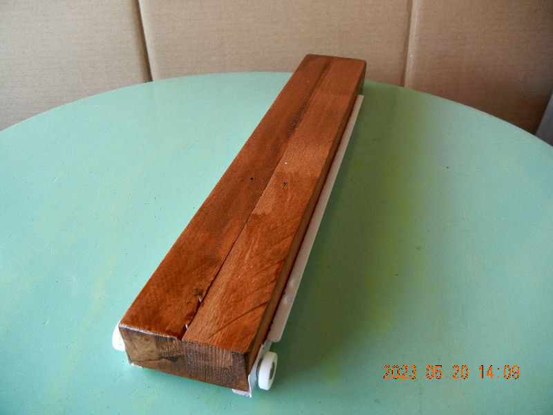
2_drawer.jpg
It's so called a drawer table. The photo shows the drawer on which is attached the top board.

―2/7―

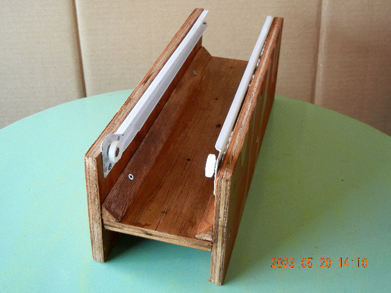
3_housing.jpg
This is the housing of the drawer(upside down) to be fixed under the living room table.

―3/7―

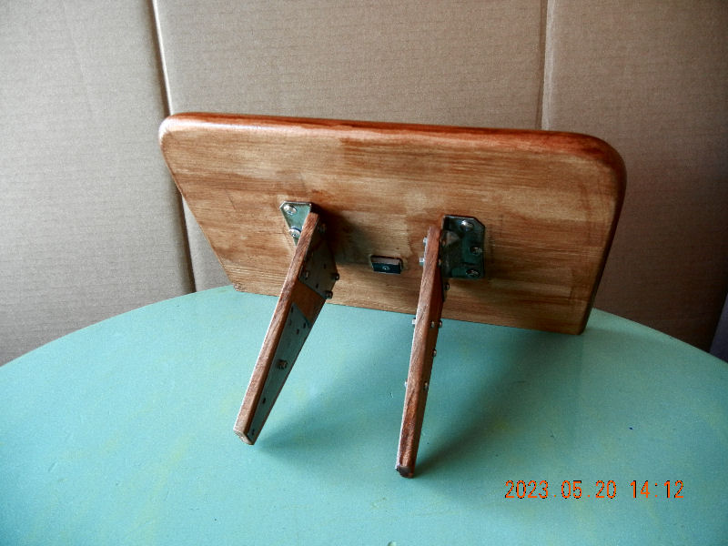
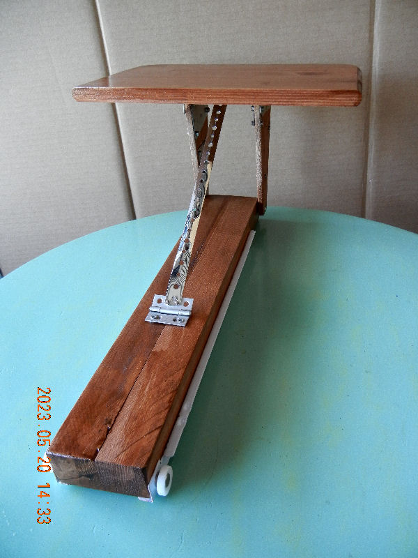
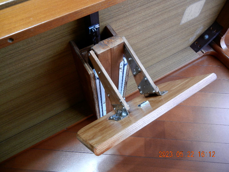
4_top holder.jpg
The whole view of the drawer table. The top board, turning around about 120 degrees downward, can be retracted inward when not used.

―4/7―

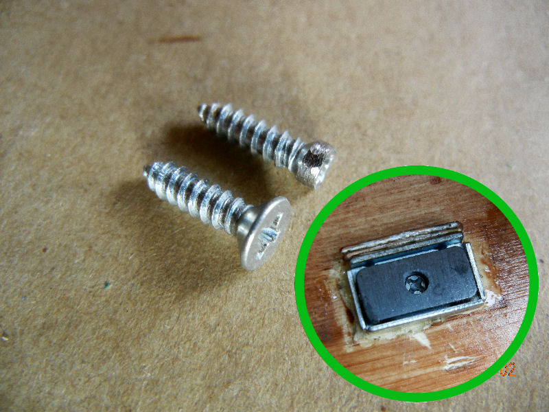
5_remodeling screw.jpg
I used a magnet article to hold the table board at its place but it wasn't made to be fit up with an ordinary screw. So I grinded a screw head smaller as shown in the photo. I can't understand why they made the hole so small? It's very unkind.

―5/7―

6_retracted table.jpg
The table is tetracted as shown in the photo.

―6/7―

0_sofa table.jpg
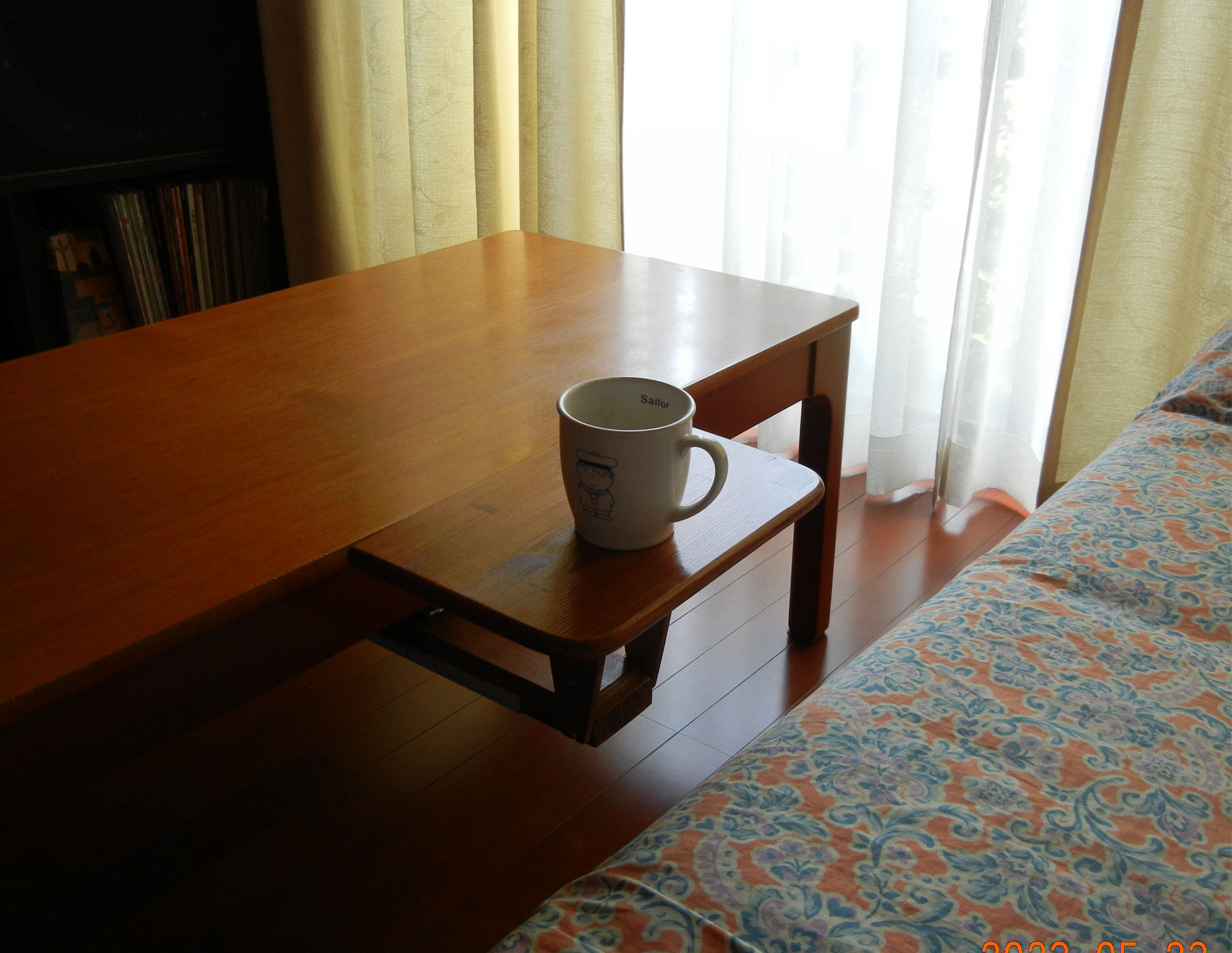
The sofa table in use. Now I'm free from the disaster putting back a mug easily after each sipping. Is it something like a lazy Suzan?  

―7/7―

Return to the list

All rights reserved by JA2TVO